
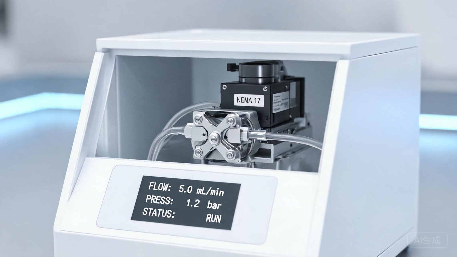
When design engineers integrate a peristaltic pump into laboratory, diagnostic, or analytical equipment, the motor and drive architecture often determines whether the system meets accuracy, noise, and lifetime targets. Stepper motor peristaltic pumps have become a common choice for OEM manufacturers who need precise speed control, repeatable dosing, and direct interface with PLCs or embedded controllers. Unlike simple brushed DC pumps, a stepper-driven system requires the engineer to specify not only the pump head and tubing, but also the driver, control protocol, mounting geometry, and thermal environment.
This guide addresses the practical questions that arise during OEM integration: how to match the drive architecture to the application, which control interface fits the existing instrument electronics, what mechanical constraints affect pump selection, and how to evaluate a supplier’s ability to support a production program. The focus is on equipment that demands controlled fluid transfer rather than simple on/off circulation.
What Engineers Should Define Before Selecting a Stepper Motor Pump
Before comparing products, the engineering team should document the fluid-handling requirements and the electrical environment of the host instrument. Flow rate range, dosing accuracy, and acceptable pulsation level determine whether a stepper motor is necessary at all. For applications such as reagent dispensing in diagnostic analyzers or media transfer in bioreactors, stepper control provides the fine speed resolution that supports consistent droplet volume or linear flow profiles.
The electrical interface is equally important. Some instruments already include a motion controller with step/direction outputs, making a stepper motor pump a natural fit. Others rely on analog signals from a PLC or a microcontroller DAC. A mismatch between the instrument’s existing control architecture and the pump’s input requirements can add weeks of firmware redevelopment.
Thermal and physical envelopes also constrain selection. A peristaltic pump driver that mounts directly on the rear of a NEMA 17 motor may save space, but the engineer must confirm that the combined motor-driver assembly fits within the allocated volume and that heat dissipation does not raise internal temperatures beyond the driver’s rated range. YOORAIN’s PMD 6P driver, for example, operates from −20°C to 80°C and provides 0–4 A peak current with 128 microstepping, which suits compact instrument enclosures when adequate airflow or conduction cooling is provided.
Comparing Drive Options: Stepper, DC, and Brushless DC
Not every OEM application needs a stepper motor. Brushed DC motors remain common in cost-sensitive portable devices, while brushless DC motors offer longer life than brushed units without the control complexity of a full stepper system. The decision depends on accuracy requirements, duty cycle, noise budget, and system cost.
Stepper motors excel when the application requires precise speed control across a wide range, low-speed operation without cogging, or position-based dispensing. Microstepping drivers can smooth rotation and reduce mechanical vibration, which matters in laboratory environments where acoustic noise affects personnel or sensitive measurements. Brushed DC motors are simpler to drive but exhibit brush wear and audible commutation noise. Brushless DC motors eliminate brush wear and run quietly, yet they require electronic commutation controllers that add cost and firmware overhead.
| Feature | Stepper Motor | Brushed DC Motor | Brushless DC Motor |
|---|---|---|---|
| Speed control resolution | 0.1–1 rpm typical | Coarse PWM control | Medium PWM control |
| Positioning accuracy | High (open or closed loop) | Low | Medium |
| Noise at low speed | Very low with microstepping | Moderate brush noise | Low electronic commutation noise |
| Driver complexity | Requires stepper driver | Simple H-bridge | Requires ESC or dedicated driver |
| Typical OEM cost | Moderate | Low | Moderate to high |
| Lifetime | 10,000+ hours | 2,000–5,000 hours (brush wear) | 10,000+ hours |
For instruments that dose reagents in microliter increments or that ramp flow smoothly during a chromatography separation, the resolution and low-speed torque of a stepper motor often justify the additional driver cost. For high-volume transfer where ±5% accuracy is acceptable, a brushed DC micro peristaltic pump range may be the more economical path.
Control Interface and Communication Protocol Considerations
The interface between the instrument controller and the pump driver determines how easily the pump integrates into the existing software architecture. OEM engineers typically encounter four categories of control interface: analog voltage, analog current, digital pulse, and serial communication.
Analog voltage control (0–5 V or 0–10 V) offers the simplest integration. The instrument’s DAC output sets pump speed proportionally. This approach works when the application only needs variable flow without precise position feedback. Analog current (4–20 mA) is preferred in industrial environments because current loops resist electrical noise over longer cable runs.
Digital pulse control uses step and direction signals. The instrument’s motion controller or microcontroller generates a pulse train at a frequency proportional to desired speed. Direction logic sets rotation sense. This method gives the host full control over acceleration profiles and positional moves, which is valuable when the pump must dispense exact volumes by running a defined number of steps.
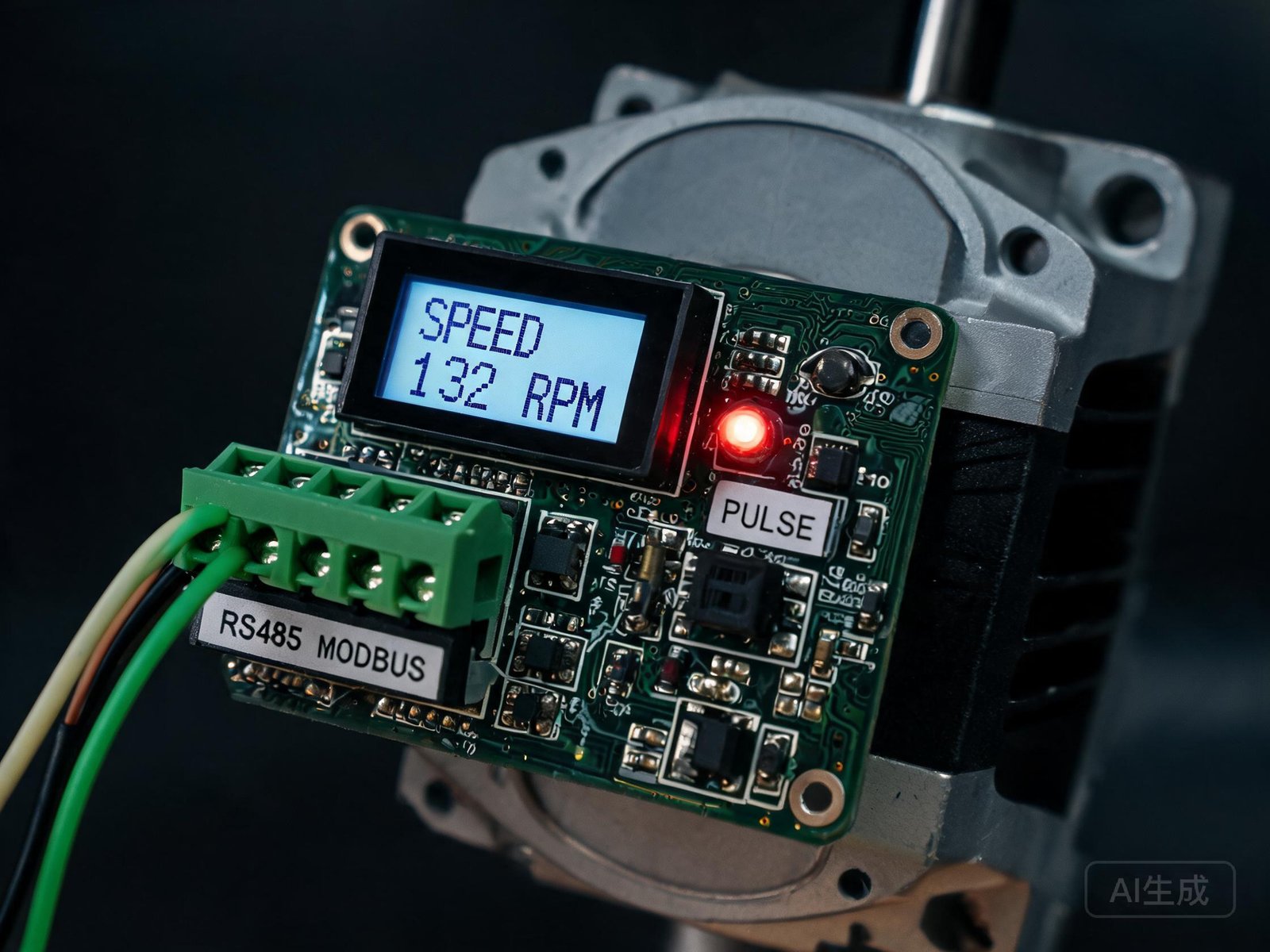
Serial communication, most commonly MODBUS protocol specifications over RS485, allows multiple pumps to share a two-wire bus. The host PLC or computer addresses each pump individually, sets speed, queries status, and receives alarm flags. MODBUS RTU is widely supported by industrial controllers and simplifies cabling in multi-channel instruments such as parallel reactor systems or multi-reagent diagnostic analyzers.
| Interface Type | Signal Format | Typical Use Case | Integration Effort |
|---|---|---|---|
| Analog voltage | 0–5 V or 0–10 V | Basic speed control | Low |
| Analog current | 4–20 mA | Industrial PLC integration | Low |
| Digital pulse | Step/direction | Precise position and speed control | Medium |
| Serial communication | RS485 MODBUS RTU | Multi-pump networked systems | Medium |
| TTL logic | Start/stop/direction | Simple on/off control | Low |
When selecting a driver, confirm that the available interface matches the instrument’s controller outputs. A driver that supports both step/direction and RS485, such as the PMD 6P, gives the engineering team flexibility to change control architecture during prototype development without replacing the motor or pump head.
Mechanical Integration and Mounting Requirements
The mechanical interface between pump and instrument chassis is often underestimated. Peristaltic pumps for OEM use are commonly offered in bare pump-head form, as motor-pump assemblies, or as peristaltic pump with housing enclosures that include the driver, display, and mounting feet. The choice depends on how much mechanical design the OEM team wants to perform in-house.
A bare pump head on a custom bracket offers the smallest footprint and the most freedom in tubing routing. The engineer must design the motor mount, provide the driver PCB, and manage cable routing. This approach suits high-volume programs where enclosure space is limited.
A housed unit arrives as a complete assembly with a stainless steel enclosure, front panel controls, and standardized mounting points. The OEM engineer supplies DC power and control signals, then bolts the housing to the instrument frame. The enclosed peristaltic pump system with SUS304 housing and LCD interface supports YZ15, YZ25, and DG pump heads across flow ranges from 0.03 ml/min to 2600 ml/min.
Tubing routing deserves attention during mechanical design. The tube must enter and exit the pump head without sharp bends that cause kinking or accelerated fatigue. Silicone and BPT tubes common in laboratory equipment typically require a minimum bend radius of approximately ten times the outer diameter. The engineer should also plan for tube replacement access.
Supplier Technical Capability Evaluation
Selecting a pump supplier for an OEM program involves more than comparing catalog specifications. The supplier must be able to support the integration process, respond to mechanical or electrical customization requests, and maintain consistent quality across production batches.
Engineers should evaluate whether the supplier provides detailed mechanical drawings, 3D models, and interface documentation. A supplier that offers a OEM peristaltic pump customization program can adapt pump heads, motor types, and driver firmware to match the instrument’s specific requirements. For example, a diagnostic equipment manufacturer may need a custom tubing connector geometry or a modified roller gap to achieve a specific compression ratio.
Electrical support is equally important. The supplier should provide a clear register map for MODBUS communication, timing diagrams for step/direction inputs, and application notes for grounding and shielding. Drivers that mount directly on NEMA 17 or NEMA 23 motors simplify wiring, but the supplier must confirm that the driver-motor combination has been validated for continuous operation at the intended duty cycle and temperature.
Quality consistency affects every production unit. Ask the supplier about incoming inspection protocols for motors, driver PCBs, and tubing. Inquire whether they perform 100% functional testing or statistical sampling, and whether they can provide traceability records for critical components. For instruments sold into regulated markets, IEC 61010-1 safety requirements for electrical equipment and USP standards for pharmaceutical applications may influence the documentation and testing the supplier must support.
Prototype Testing and Validation
Once a pump and driver are selected, prototype validation should verify mechanical fit, electrical compatibility, and fluidic performance under realistic conditions. Mechanical fit checks include mounting hole patterns, overall dimensions, and tubing path clearance. Electrical compatibility testing confirms that the instrument controller can reliably drive the pump across the full speed range without signal integrity issues.
Fluidic performance validation measures flow rate accuracy, repeatability, and pulsation level at multiple speeds with the actual fluids the instrument will handle. NIST fluid metrology resources describe gravimetric and volumetric calibration methods. A common approach is to collect pumped fluid over a timed interval, weigh the sample on a calibrated balance, and compare the measured volume to the target.
Thermal testing is often overlooked. The pump motor and driver generate heat during continuous operation. In a closed instrument enclosure, this heat can raise internal temperatures enough to affect driver reliability. Prototype testing should include thermocouple measurements at the driver heat sink and motor casing during worst-case ambient conditions.
Noise and vibration testing matters for laboratory instruments installed near operators. A K15 micro peristaltic pump with optimized roller geometry and microstepping drive can operate below 45 dB at typical laboratory speeds, matching the acoustic environment of most analytical instruments.
OEM Integration Checklist
The following checklist summarizes the technical items an engineering team should confirm before finalizing a stepper motor peristaltic pump for an OEM instrument.
| Category | Item to Confirm | Why It Matters |
|---|---|---|
| Electrical | Voltage compatibility (9–48 VDC typical) | Ensures driver matches system power supply |
| Electrical | Control signal type (step/dir, analog, RS485) | Determines PLC or microcontroller interface |
| Mechanical | Pump mounting footprint (NEMA 17/42 mm or custom) | Confirms physical fit inside instrument enclosure |
| Mechanical | Tubing routing and minimum bend radius | Prevents kinking and premature tubing wear |
| Thermal | Operating temperature range (−20°C to 80°C typical) | Validates driver reliability under instrument conditions |
| Software | MODBUS register map or step timing documentation | Enables custom software integration |
| Validation | Flow accuracy test protocol | Confirms dosing meets application requirements |
| Quality | Supplier incoming inspection and functional test records | Ensures production consistency across batches |
Stepper motor peristaltic pumps offer OEM engineers a balance of precision, control flexibility, and production maturity. The integration effort focuses on matching the electrical interface to the instrument controller, confirming mechanical fit within the enclosure, and validating flow performance under actual operating conditions. Suppliers who provide detailed documentation and consistent quality reduce development risk for laboratory, diagnostic, and analytical equipment.
For OEM equipment projects, sharing your required flow range, control interface, mounting constraints, and target application helps suppliers recommend a suitable pump and driver configuration. Contact YOORAIN to discuss the mechanical and electrical requirements of your instrument.