
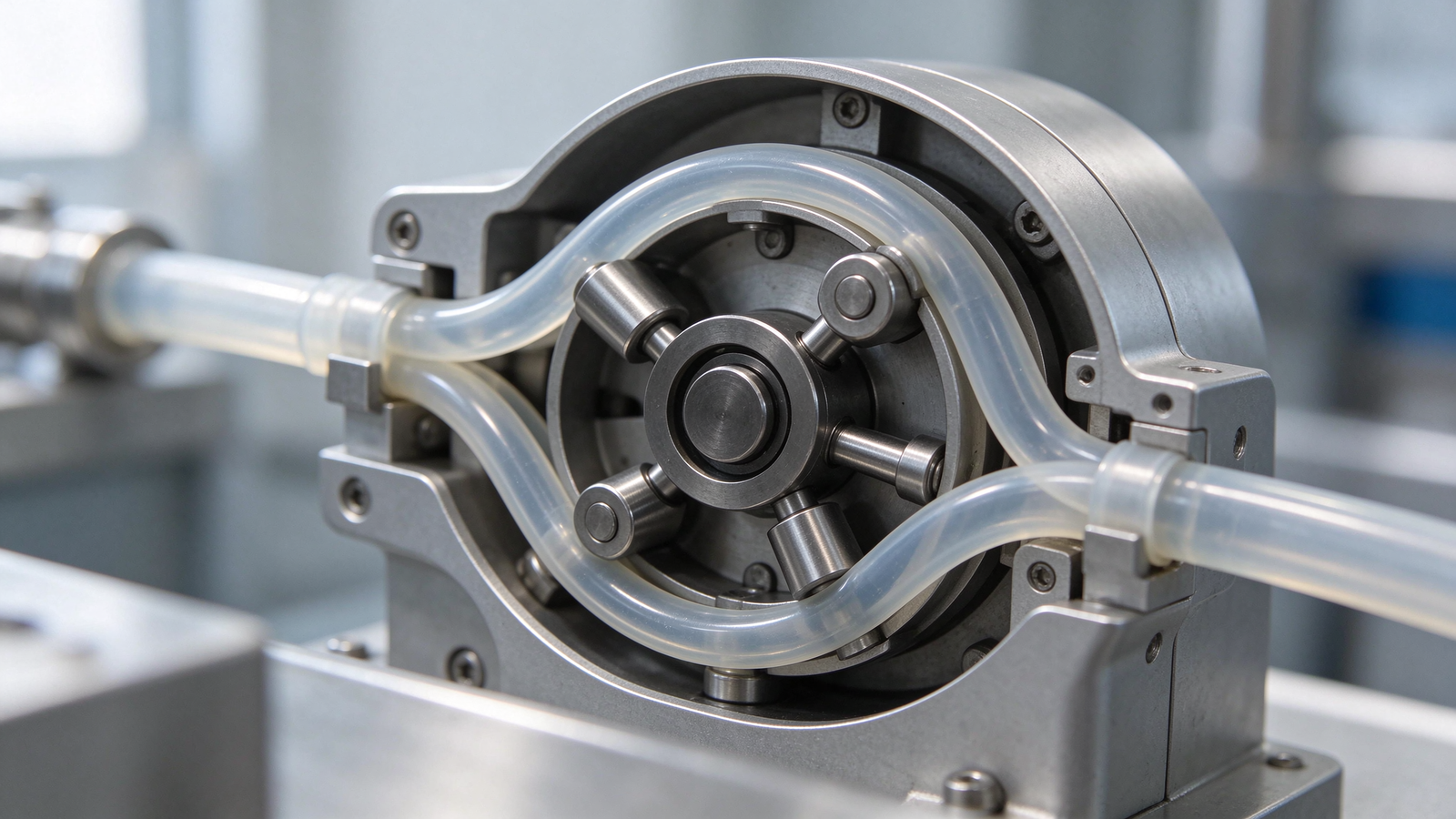
Specifying or troubleshooting a peristaltic pump becomes clearer once the action inside the head is understood. The pump does not rely on impellers, gears, or check valves to move the fluid; it squeezes a flexible tube in a moving sequence and lets the tube spring back to draw in the next charge. That one principle explains why the fluid stays isolated from the internals, why the output moves in steps as each roller passes, why the tube is the main consumable, and why flow can slip when the tube wears or the back-pressure rises. This engineering guide walks through the peristaltic action stage by stage, the components that make it work, and the practical consequences for flow, accuracy, and maintenance.
The Peristaltic Action in Four Stages
Inside the head, a rotor carries rollers that follow the curved wall of the housing. As the rotor turns, each roller presses the flexible tube flat at its point of contact, occluding the bore and pushing the fluid ahead of it. Behind the released roller, the tube returns to its round shape, expanding the bore and drawing fluid from the suction side. The next roller repeats the sequence, so the fluid column travels along the tube in a series of pushed charges rather than a smooth impeller stream.
| Stage | What happens in the tube | Engineering note |
|---|---|---|
| Roller approach | Roller reaches the tube and begins closing the bore | Fluid ahead starts moving toward the discharge side |
| Occlusion | Tube is compressed flat at the roller, sealing the bore at that point | The sealed point separates suction from discharge along the tube |
| Release | Roller passes and lifts off the tube | Compression moves to the next roller on the rotor |
| Tube recovery | Tube springs back to round, drawing in the next charge | Recovery depends on material elasticity and condition |
What Makes Up the Pump
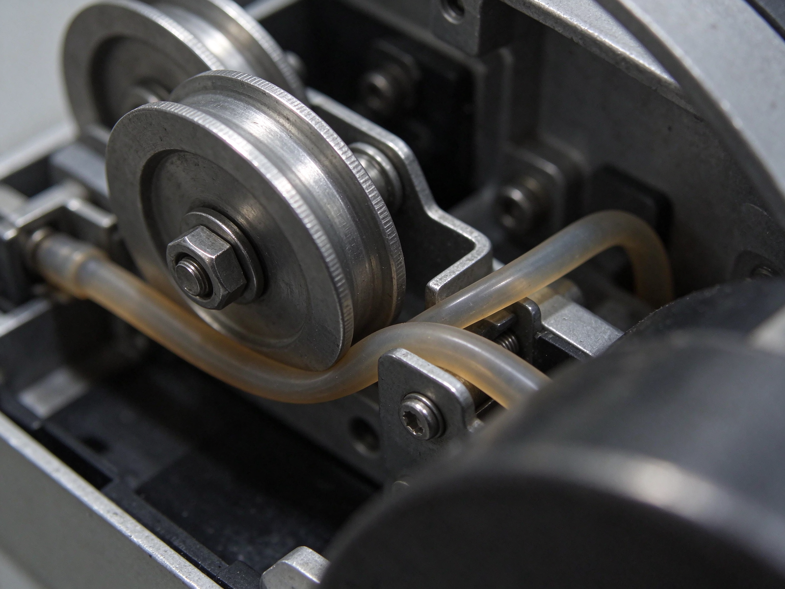
A peristaltic system has a small number of core parts. The head holds the housing, rotor, and rollers and sets the compression path. The rotor and rollers carry the compression around the tube. The tube is the only fluid-contact part; it carries the fluid through the head and returns to shape after each roller passes. The drive turns the rotor at the chosen speed and provides the control arrangement. Fittings and connections join the tube to the suction and discharge lines. Because the fluid never leaves the tube, there are no impeller vanes, gears, or valve seats in the wetted path.
That isolation is a defining feature. The process fluid contacts only the bore and end fittings of the tube, which simplifies compatibility review to the tube material and the fittings, and keeps the fluid away from seals and chamber surfaces that could hold residue. It also means the tube, rather than a chamber seal, is the part that ages with the duty.
How Flow Is Produced
On each rotor revolution, the rollers displace a fixed volume of tube bore along the compression path. The theoretical output per revolution is set by the tube bore and wall geometry and the rotor layout; the actual delivered flow is that displacement multiplied by rotor speed, then adjusted for what the fluid and line do in practice. Several factors keep the real flow from matching a simple speed reading.
| Factor | Effect on delivered flow |
|---|---|
| Tube bore and wall | Sets the displacement available per compression cycle |
| Rotor speed | Main adjustment: more revolutions deliver more volume per unit time |
| Back-pressure | Higher discharge pressure increases the chance of fluid slipping back toward suction |
| Fluid viscosity | Thicker fluid draws more slowly and can limit how fast the head fills each cycle |
| Tube condition | A worn, softened, or fatigued tube recovers less fully and slips more |
| Suction condition | Leaks, kinks, or air in the suction line reduce the charge drawn each cycle |
The drive arrangement for a given head can range from a fixed-speed unit to an adjustable-speed or signaled drive; the peristaltic pump driver sets how the rotor speed is controlled. Small instrument duties use a micro peristaltic pump, general feed a small peristaltic pump head, and compact equipment a mini peristaltic pump arrangement; the peristaltic pump tube completes the fluid path.
Tube Recovery, Fatigue, and the Consumable Role
Every roller cycle bends and releases the tube wall. The material has to stretch open under compression and spring back on release to draw the next charge. Over thousands of cycles the tube fatigues: the wall thins at the compression path, the surface cracks, or the material hardens and loses elasticity. When recovery slows, the bore does not fill as fully and the delivered volume drops. This is why the tube is treated as the main consumable on a peristaltic, and why replacement interval depends on chemical, concentration, temperature, abrasiveness, and run hours.
Tube material choice trades elasticity, chemical resistance, and wear. A material that resists the process fluid but recovers poorly, or one that recovers well but swells in the chemical, will not hold its dosing life. Compatibility should be checked against the actual fluid at operating temperature rather than assumed from a generic rating.
Slip, Pulsation, and Practical Accuracy
Slip is the small amount of fluid that works back toward the suction side under discharge pressure instead of moving out the discharge. It grows with back-pressure, a fatigued tube, or a poor seal at the occlusion point. Slip is why a peristaltic dose should be verified by dispensing and measuring a known volume, not read off the speed setting alone. The NIST measurement practice describes weighing and volume checks that make that verification consistent.
Pulsation follows the roller sequence. Each roller pushes a step of fluid, so the discharge flow rises and falls between rollers rather than running perfectly smooth. The effect is more noticeable at low speeds and with viscous fluids; line layout, accumulators, and hose flexibility are the usual ways to even the output on a sensitive feed.
Actual accuracy on a peristaltic depends on a matched tube, a sound head, a clean suction path, and calibration after service. A fresh pump on a compatible tube, properly primed and within its pressure range, repeats its dose; drift usually points back to tube condition, slip, or suction air rather than the rotor itself.
How the Principle Drives Maintenance
Because the action centers on the tube, maintenance centers on inspecting and replacing it, checking that rollers turn freely and the tube seats centrally, and confirming the compression path has no wear that pinches or cuts the tube. The motor-driver operating manual and driver reference cover the drive side; the head and tube side follow the occlusion cycle described here. After a tube change, re-calibrate the delivered volume before putting the pump back into service.
Frequently Asked Questions
Does a peristaltic pump have check valves? No. The occlusion point at each roller separates suction and discharge along the tube, so there are no inlet or outlet valve seats in the fluid path. That is what lets it pass some particles without a valve trapping them.
Why does the tube wear only in part of the head? The compression and release happen along the roller path, so fatigue concentrates where the tube repeatedly flattens and recovers. Inspect that arc first during service.
Can I judge flow from the drive speed alone? Speed sets the displacement rate, but actual output shifts with slip, tube condition, viscosity, and back-pressure. Verify the dose by measuring a dispensed volume.
What causes the pulsing feel at the outlet? It is the roller sequence: each roller releases a pushed charge in turn. On a sensitive line, line layout or dampening measures can even the flow.
Why does a new tube sometimes deliver a different volume? A fresh tube has different elasticity and seating than the old one, so the calibration established before a tube change may not carry over. Re-check the volume after replacement.
If you are working through how a peristaltic will fit a dosing or transfer duty, contact YOORAIN with the fluid, viscosity, target flow, back-pressure, and control arrangement. We can walk through the head, tube material, and drive options that match the principle to your line.