
Most OEM instruments that fail in the field do not fail because a single component was defective. They fail because the fluid path—the complete chain of reservoir, pump, tubing, fittings, valves, and sensors—was never engineered as a system. A peristaltic pump specified in isolation may meet its datasheet flow range perfectly, yet still deliver unstable reagent volumes once it is connected to a ten-meter tubing run, a viscous fluid, and a dispense needle that adds backpressure the pump was never tested against. Treating the fluid path as an afterthought is the most common root cause of accuracy drift, premature tubing failure, and validation rework in OEM instrument programs.
This article walks through the complete engineering workflow for designing an OEM fluid path around a peristaltic pump: how to translate application requirements into pump and tubing specifications, how to make architectural decisions about drive and control, how to design the mechanical layout to avoid the classic failure modes, how to calibrate and validate the system, and how to document everything so the design survives regulatory review. The guidance applies whether the end product is an in vitro diagnostic analyzer, a laboratory automation platform, a fermentation skid, or a portable environmental sampler.
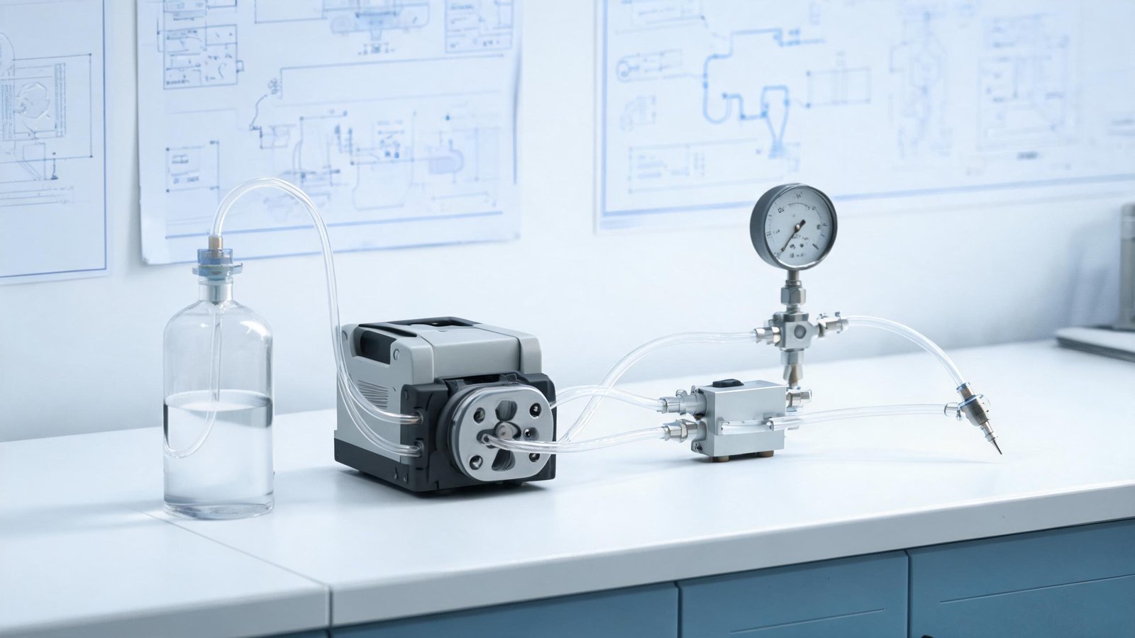
Step 1: Define the Fluid Path Requirements Before Selecting Any Component
The single most expensive mistake in fluid path design is starting with a pump model and working backward. Start instead with a written fluid path requirements specification. At minimum, this document should capture six categories of requirement.
Fluid identity and properties. Record every fluid the path will contact, including cleaning agents and sterilants. For each fluid, document viscosity range across the operating temperature window, specific gravity, vapor pressure, surface tension, chemical aggressiveness, and whether the fluid is shear-sensitive, particulate-laden, light-sensitive, or prone to crystallization. A pump that handles water-like buffers flawlessly may deliver 15 percent low when the same instrument runs a glycerol-based reagent at 10 degrees Celsius, because viscosity directly changes how the tubing refills after each roller pass.
Dosing performance targets. Specify the required dose volume range, the accuracy target (for example, ±2 percent of reading), the repeatability target (for example, coefficient of variation below 1 percent), and the minimum dispense increment. Distinguish between accuracy and repeatability explicitly: a system can be repeatable but inaccurate, and the two failure modes have different root causes and different fixes.
Throughput and duty cycle. Define the number of dispense cycles per hour, per day, and per year. This drives tubing life calculations, motor thermal design, and preventive maintenance intervals. A pump running 200 cycles per day lives in a completely different reliability regime than one running 20,000 cycles per day.
Environmental envelope. Capture ambient temperature range, humidity, altitude (which affects suction lift), vibration exposure, and cleaning or washdown requirements. Altitude is frequently forgotten: a pump specified to self-prime at sea level may fail to prime reliably at 2,000 meters because the available atmospheric driving pressure is roughly 20 percent lower.
Regulatory and quality framework. Determine early whether the end device falls under FDA 21 CFR Part 820 design controls, ISO 13485 quality system requirements, IVDR in Europe, or simply internal customer quality standards. This decision changes the documentation burden by an order of magnitude. Under FDA design control requirements in 21 CFR 820.30, the fluid path requirements specification becomes a formal design input document that must be reviewed, approved, and traceable to verification activities.
Service and lifetime expectations. Define the target instrument lifetime, the acceptable maintenance interval, who performs maintenance (trained service engineer versus end user), and the maximum allowable service time. A fluid path designed for annual tubing replacement by a field technician has different routing, clamping, and access requirements than one designed for user-replaceable consumables.
Step 2: Characterize the Fluid Experimentally
Datasheet fluid properties are starting points, not specifications. Two reagents with identical nominal viscosity can behave very differently in a peristaltic pump because of viscoelastic effects, surface wetting differences, and temperature sensitivity. Before finalizing the pump and tubing selection, run a simple experimental characterization.
Measure the fluid’s viscosity at the minimum, nominal, and maximum operating temperatures using a rotational viscometer. If the fluid is non-Newtonian, measure at the shear rates that correspond to your actual tubing flow velocity—typically in the range of 100 to 10,000 reciprocal seconds for small-bore peristaltic tubing. Measure specific gravity, because gravimetric calibration methods convert mass to volume using density, and a density error propagates directly into flow error. If the fluid is volatile, quantify evaporation rate at room conditions; volatile fluids require sealed reservoirs and vapor-tolerant priming sequences.
Most importantly, run a chemical compatibility immersion test with the candidate tubing materials. Immerse tubing samples in each fluid at the maximum operating temperature for at least 72 hours—ideally two weeks for long-life applications—and measure weight change, dimensional change, hardness change, and tensile property change. A weight gain above roughly 10 percent or a hardness change above roughly 10 Shore A points usually predicts shortened tubing life. This test routinely disqualifies tubing materials that look acceptable on generic chemical resistance charts, because charts rarely account for the combined effect of the fluid, the temperature, and the mechanical stress of repeated occlusion.
Step 3: Specify the Pump as a System Component, Not a Standalone Device
With requirements and fluid data in hand, the pump specification can be written properly. The critical insight is that the pump’s performance in the instrument depends on the system around it, so the specification must define the test conditions, not just the pump.
| Specification Item | What to Define | Common Specification Error |
|---|---|---|
| Flow rate range | Required min/max flow with the actual tubing, fluid, and backpressure | Specifying only the pump’s theoretical maximum flow |
| Accuracy and repeatability | Numerical targets plus the test method and fluid | Writing “high accuracy” without a test method |
| Operating backpressure | Maximum pressure at the dispense point including tubing losses | Assuming zero backpressure because the datasheet says so |
| Suction condition | Suction lift height, reservoir position relative to pump | Ignoring suction lift until first article testing |
| Duty cycle | On/off pattern, cycles per day, continuous run duration | Specifying only continuous rating for an intermittent application |
| Tubing life target | Minimum hours or cycles between replacements | Leaving tubing life unspecified, then discovering 200-hour life in the field |
| Noise limit | Maximum dBA at 1 meter in the instrument enclosure | Specifying pump noise in free air instead of installed noise |
When sizing the pump, apply a deliberate derating. Do not operate the pump at its maximum rated speed to achieve the nominal flow requirement; instead, select a pump and tubing combination that delivers the nominal flow at 50 to 70 percent of maximum speed. This reserves headroom for viscosity variation, tubing aging (which reduces flow as the bore relaxes), and manufacturing tolerances, and it directly extends tubing life because fatigue life scales strongly with speed.
For compact instruments, a micro peristaltic pump in the K15 class covers microliter to low milliliter dosing, while a small pump in the K25 class handles moderate transfer duties. Selecting between them should be based on the required flow at the derated operating point, not on which one can theoretically reach the flow at full speed.
Step 4: Engineer the Tubing as a Consumable Subsystem
In a peristaltic fluid path, the tubing is not an accessory—it is the pump chamber, the valve, and the wetted flow path combined. Tubing decisions drive accuracy, life, chemical compatibility, and regulatory burden more than any other single choice.
Bore diameter and wall thickness. The bore sets the displacement per revolution; the wall thickness sets the occlusion behavior and pressure capability. Smaller bores give finer resolution and better low-flow accuracy but lower maximum flow and higher sensitivity to particulate blockage. Larger bores give higher flow and better tolerance of viscous fluids but coarser resolution. Choose the smallest bore that comfortably meets the maximum flow requirement at the derated speed, because resolution and accuracy both improve as the required flow occupies more of the pump’s control range.
Material selection. Match the tubing polymer to the full fluid list, including cleaning agents. Platinum-cured silicone is the default for aqueous, biocompatible applications because of its purity, flexibility, and low extractables. PharMed-type thermoplastic elastomers offer longer flex life and better resistance to oxidizing agents. Fluoroelastomers resist aggressive organic solvents but have higher hardness and shorter flex life. The immersion test from Step 2 is the decision tool; chemical resistance charts are only a screening filter.
Dimensional tolerance. Flow rate is proportional to the square of the bore diameter, so a ±0.05 mm tolerance on a 1.6 mm bore produces roughly a ±6 percent flow variation between tubing lots. For accuracy-critical applications, specify tighter-than-standard bore tolerances and require the tubing supplier to provide lot-level dimensional data. This single specification eliminates one of the most common causes of batch-to-batch calibration drift in OEM instruments.
Tubing life prediction. Tubing life is primarily a fatigue phenomenon driven by the number of occlusion cycles, modified by speed, temperature, chemical exposure, and occlusion depth. Request accelerated life test data from the supplier under conditions matching your application, and convert the data to a maintenance interval with a safety factor of at least two. For instruments where tubing failure has safety or quality consequences, the risk analysis required by ISO 14971 risk management for medical devices should treat tubing rupture as an identified hazard with defined mitigations such as leak detection or scheduled replacement.
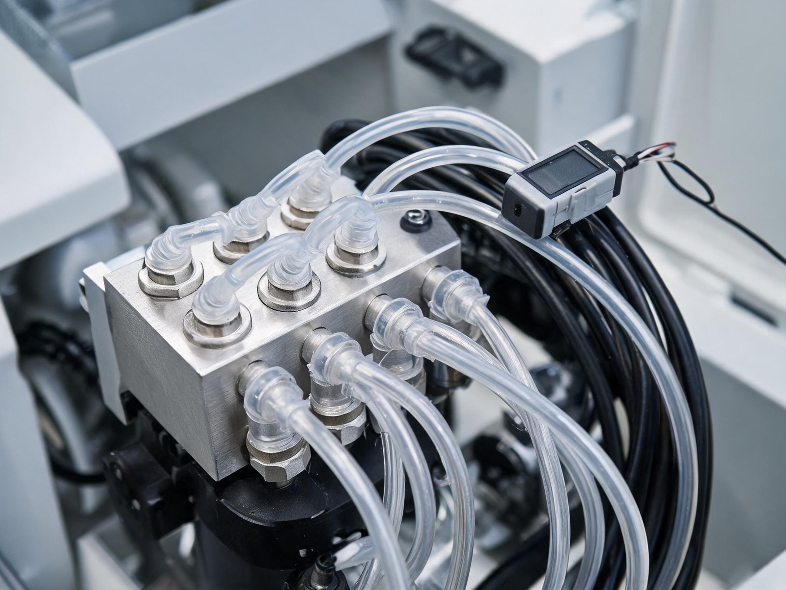
Step 5: Design the Drive and Control Architecture
The drive architecture determines how precisely the pump can be controlled, how it behaves under varying load, and how easily it integrates with the instrument’s main controller.
Motor selection. Stepper motors dominate OEM peristaltic applications because they provide open-loop position control with discrete resolution, which maps naturally to dispensed volume. A 200-step-per-revolution stepper on a pump head delivering 0.5 mL per revolution gives a theoretical resolution of 2.5 microliters per step before microstepping. DC brush motors are cheaper but require an encoder and closed-loop control to achieve comparable volume resolution, and brush wear limits life. Brushless DC motors offer long life and smooth operation at a higher driver cost.
Microstepping and motion profiles. Microstepping improves flow smoothness and reduces pulsation-related noise but does not increase true positioning accuracy proportionally, because microstep torque is nonlinear. For dosing applications, use acceleration and deceleration ramps to avoid stalling the rotor when starting against backpressure, and avoid running in resonance regions that amplify vibration. The resonance band of a typical small stepper sits between roughly 50 and 200 full steps per second, and operation there can triple noise and introduce missed steps.
Stall and fault detection. An encoder or back-EMF-based stall detection is strongly recommended for any application where a blocked line could cause a safety or quality issue. Without it, a stalled pump continues to consume steps while delivering nothing, and the instrument has no way to know the dispense failed. A dedicated peristaltic pump driver with integrated current limiting and fault outputs simplifies this integration and reduces the firmware burden on the main controller.
Control interface. Define whether the pump accepts step/direction signals, analog speed voltage, or a serial protocol such as RS-485 with Modbus. Serial control allows the main controller to query pump status, read fault flags, and log operating hours for predictive maintenance—capabilities that are difficult to retrofit if the architecture is fixed at step/direction only.
Step 6: Mechanical Layout—Where Most Designs Go Wrong
The mechanical arrangement of the fluid path has a larger effect on accuracy and reliability than most electrical or software decisions. Several layout rules are repeatedly learned the hard way.
Minimize suction lift and suction line length. Peristaltic pumps self-prime, but priming performance degrades with suction height and line length. Place the pump at or below the reservoir fluid level whenever possible. Every meter of suction lift subtracts roughly 0.1 bar from the effective driving pressure, and long suction lines increase the compressible air volume that the pump must displace before liquid reaches the rollers.
Keep the discharge line short and large enough. Discharge line resistance appears as backpressure at the pump. Backpressure reduces flow, increases tubing wear, and—at high enough values—can cause the tubing to balloon and eventually rupture. Size the discharge tubing so that total system backpressure at maximum flow stays well below the pump’s pressure rating, and verify the calculation with a pressure measurement on the first prototype.
Respect the minimum bend radius. Sharp bends kink the tubing, restrict flow, and create local stress concentrations that shorten life. A typical minimum bend radius is four to six times the tubing outer diameter. Route tubing with smooth, generous curves, and use formed fittings rather than tight bends wherever the layout allows.
Isolate vibration. The roller mechanism generates periodic mechanical excitation at the roller pass frequency. In analytical instruments, this vibration can couple into optical benches, balances, or acoustic sensors. Mount the pump on elastomeric isolators, and avoid rigidly coupling the pump plate to resonant panels. Measure installed noise and vibration on the prototype, not just pump noise in free air.
Design for service access. The fluid path will be serviced. If tubing replacement requires removing three subassemblies and a wiring harness, the mean time to repair balloons and the probability of reassembly error increases. A pump supplied in a dedicated housing with front-loading tubing access typically cuts service time dramatically compared with a pump buried behind other modules.
Step 7: Sensing and Closed-Loop Control
Open-loop peristaltic dosing is adequate for many applications, but adding the right sensor at the right point converts the fluid path from a best-effort system into a verifiable one.
Flow sensing. Inline flow sensors—thermal, Coriolis, or ultrasonic—allow true closed-loop flow control and real-time fault detection. Coriolis sensors give the best accuracy and fluid independence but at a cost that usually restricts them to high-value instruments. Thermal sensors offer a cost-effective middle ground for aqueous fluids.
Pressure sensing. A pressure sensor on the discharge line detects occlusion (rising pressure) and line rupture or disconnection (falling pressure). For IVD and pharmaceutical applications, pressure-based occlusion detection is often a required safety feature, because a blocked dispense line that goes undetected can lead to over-pressurization and tubing rupture.
Air and bubble detection. Optical or ultrasonic bubble detectors on the suction line prevent air from entering the reaction or dispense path, which is critical in diagnostic instruments where an air gap in a dispensed reagent volume is a direct analytical error.
Calibration feedback. Regardless of sensing, build in a calibration routine that periodically verifies delivered volume against a reference. The NIST fluid metrology resources describe traceable gravimetric methods in which the dispensed mass is measured on a calibrated balance and converted to volume using the fluid’s measured density—this is the reference method most often used to anchor an instrument’s internal calibration.
Step 8: Failure Mode Analysis for the Fluid Path
A structured failure mode and effects analysis (FMEA) of the fluid path is the difference between a design that is engineered and one that is merely assembled. For each element of the path, list the credible failure modes, their effects, their likelihood, and the mitigation. The table below shows a condensed example for a reagent dispensing subsystem.
| Component | Failure Mode | System Effect | Mitigation |
|---|---|---|---|
| Pump tubing | Fatigue rupture | Leak, loss of dose, possible reagent contamination | Scheduled replacement interval, leak sensor under pump |
| Pump tubing | Gradual bore relaxation | Slow downward drift of dispensed volume | Periodic recalibration, flow verification check |
| Discharge line | Partial blockage | Rising backpressure, reduced flow | Discharge pressure monitoring with alarm threshold |
| Suction fitting | Air ingress | Air bubbles in dose, under-dosing | Bubble detector, proper fitting torque specification |
| Stepper motor | Stall under overload | Silent dispense failure | Stall detection, encoder feedback |
| Driver electronics | Overcurrent shutdown | Pump stops mid-dose | Thermal design margin, status polling over serial link |
For medical and diagnostic instruments, this FMEA feeds directly into the risk management file required by ISO 14971. Even for industrial instruments, the exercise pays for itself by surfacing the failures that would otherwise appear during customer acceptance testing, where they are far more expensive to fix.
Step 9: Verification and Validation—IQ, OQ, PQ Applied to the Fluid Path
Verification confirms the fluid path was built correctly; validation confirms it performs in actual use. The pharmaceutical convention of installation, operational, and performance qualification maps cleanly onto fluid path engineering.
Installation qualification (IQ). Verify that the delivered system matches the design: correct pump model and firmware version, correct tubing material and dimensions with lot certificates, correct fittings, correct sensor calibration certificates, and correct mechanical installation per the layout drawings.
Operational qualification (OQ). Verify that the system operates to specification across its intended range. For a dosing path, this means gravimetric verification of dispensed volume at the minimum, nominal, and maximum dose settings, across the specified temperature range, with the actual fluid or a qualified simulant. Each data point should be replicated enough times—typically at least ten dispenses—to calculate both accuracy and repeatability with statistical confidence.
Performance qualification (PQ). Verify sustained performance under real operating conditions over time. A typical PQ protocol for a dosing path runs the system through repeated cycles over days or weeks, with periodic gravimetric checks to detect drift. The acceptance criteria should come from the requirements specification in Step 1, closing the traceability loop that ISO 13485 quality management requirements expect to see between design inputs and design validation.
Build the data collection for OQ and PQ into the instrument firmware from the start. Instruments that log every dispense volume, pump speed, and fault event make PQ straightforward; instruments that require manual data collection turn PQ into a labor-intensive bottleneck that teams are tempted to shortcut.
Step 10: Documentation That Survives Audit
The fluid path documentation package should be assembled as the design progresses, not reconstructed at the end. A complete package for a regulated OEM instrument typically includes the fluid path requirements specification, the component specifications with supplier certificates (tubing material certificates, pump test reports), the FMEA or risk analysis, the calibration procedure and traceability records, the OQ and PQ protocols and reports, and the service manual section covering tubing replacement and preventive maintenance.
Tubing documentation deserves special attention because the tubing is usually the highest-risk component. Retain material certifications, lot traceability records, and—where applicable—biocompatibility or extractables documentation from the tubing supplier. If the instrument is ever audited, the tubing documentation is among the first records requested, because it is the part most likely to be changed by a supplier and the part most likely to affect patient or product safety.
Frequently Asked Questions
How early in an instrument program should the fluid path be designed?
At the system architecture stage, before the mechanical chassis is fixed. Fluid path requirements drive component placement, service access, and enclosure penetrations, all of which are expensive to change once tooling is committed.
What is the most common cause of flow accuracy drift in the field?
Tubing bore relaxation from repeated occlusion, combined with lot-to-lot bore tolerance. Both are controlled by specifying tight bore tolerances, running the pump at derated speed, and implementing periodic gravimetric verification.
Does a peristaltic fluid path need closed-loop flow control?
Not always. Open-loop control with periodic calibration is sufficient for many dosing applications. Closed-loop control with an inline flow sensor becomes worthwhile when the fluid varies significantly between runs, when the accuracy target is tighter than about ±2 percent, or when a silent dosing failure would have safety or quality consequences.
How should tubing replacement intervals be set?
Base them on accelerated life test data under conditions matching the application, apply a safety factor of at least two, and then confirm with PQ data from the first production units. Track actual tubing life in the field and tighten or relax the interval based on evidence rather than leaving it fixed forever.
What should an OEM ask a pump supplier for during design-in?
Flow curves measured with the actual tubing and a representative fluid, tubing life test data, dimensional tolerances for the pump head and tubing interface, driver interface documentation, and material certificates. If you are scoping a new instrument, send YOORAIN your fluid list, target flow range, and duty cycle, and the engineering team can propose a pump and tubing configuration matched to those requirements.