
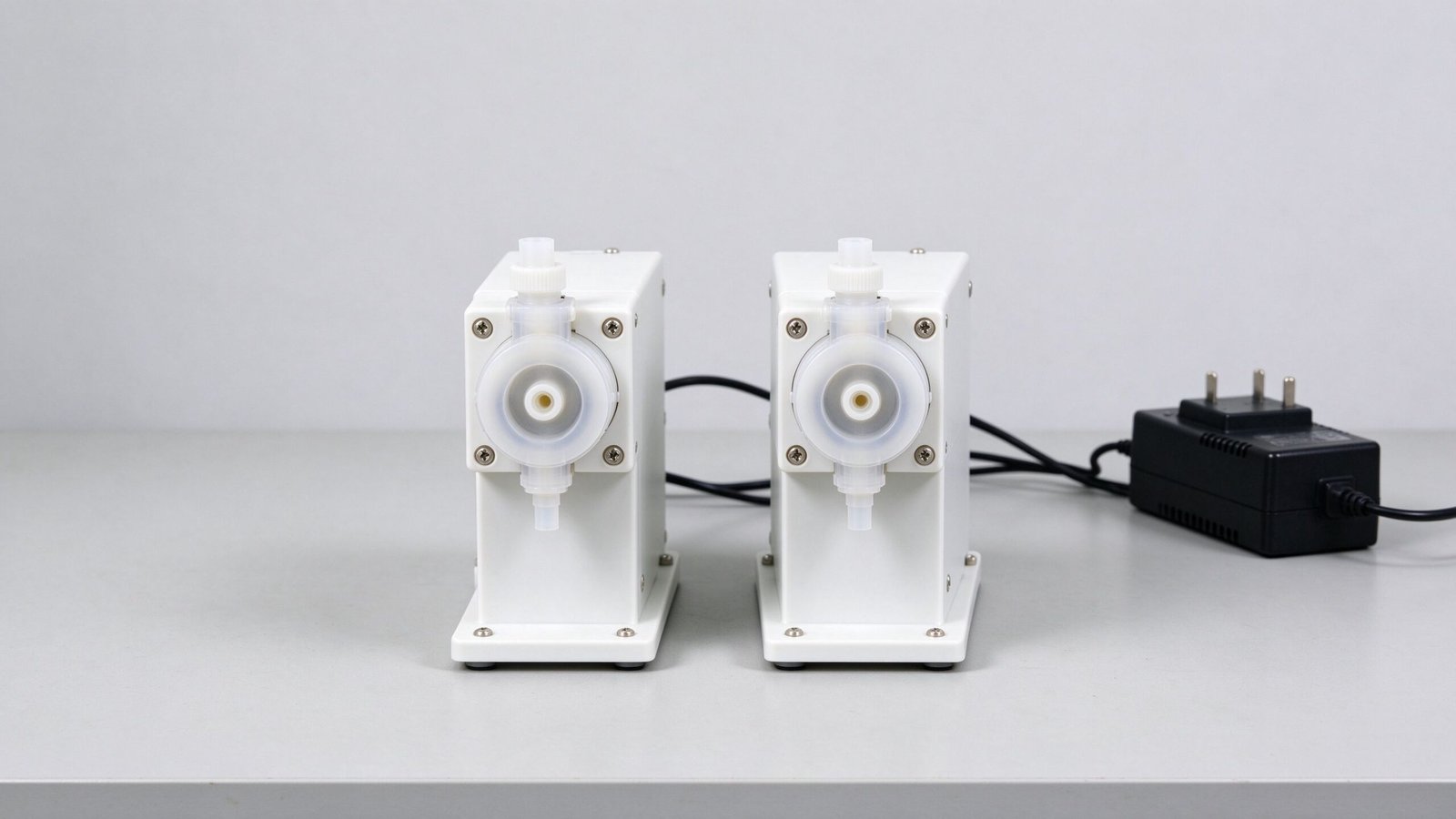
When you order a peristaltic pump, the first question after the flow rate is the voltage: 12V or 24V. It is easy to treat the choice as a footnote, but it shapes the wire size, the current draw, the battery life, the power supply, and even the noise margin of the whole instrument. This buyer guide explains the real trade-offs between 12V and 24V DC peristaltic pumps so you can pick the right voltage the first time.
The Basic Trade-Off: Current vs Voltage
Power is voltage times current. For the same pump power, a 12V motor draws roughly twice the current of a 24V motor. Higher current means thicker wires, larger connectors, more heat in the supply, and bigger voltage drops along the cable. A 24V pump draws less current for the same work, which is why industrial and continuous-duty equipment leans to 24V.
The advantage of 12V is the power source. It matches lead-acid batteries, small wall adapters, and portable gear. If your device runs on a 12V battery or a 12V supply, a 12V pump is the simple match. If your equipment already has a 24V bus, a 24V pump is the cleaner choice. The rule is to match the pump to the system rail that already exists, rather than adding a converter.
| Factor | 12V DC | 24V DC |
|---|---|---|
| Current at same power | Higher (~2x) | Lower |
| Wire size | Thicker, longer runs | Thinner, longer runs OK |
| Typical source | Battery, wall adapter | Industrial 24V bus, SMPS |
| Voltage drop along cable | More noticeable | Less |
| Heat in supply | Higher at high current | Lower |
| Best fit | Portable, battery, low power | Continuous, industrial, long runs |
Where 12V Makes Sense
Choose 12V when the device is portable, battery-powered, or runs from a small wall adapter. A 12V DC peristaltic pump drops straight into that architecture, and the lower supply voltage is safer and simpler in handheld or battery gear. The trade-off is that the wires and the supply must be sized for the higher current, especially if the pump sits some distance from the battery or adapter.
For low-power, intermittent pumps this rarely matters. A small micro pump draws little current, and a short run of thin wire is fine. The 12V choice becomes a problem only when the pump is larger, the cable is long, or the battery is small relative to the current draw. Then the voltage sag under load can slow the pump and change the delivered volume.
Where 24V Makes Sense
Choose 24V for industrial equipment, continuous dosing panels, and anything with long cable runs. A 24V dosing pump draws half the current of an equivalent 12V pump, so the supply, wires, and connectors are smaller and the voltage stays steady along the line. 24V is also the standard control voltage in industrial cabinets, so the pump shares the existing rail with sensors and PLCs.
For continuous-duty metering, the lower current also means less heat in the driver and supply, which helps reliability in an enclosed panel. Stepper and BLDC drivers that accept a 24V supply are common in this space, and the matching peristaltic pump driver is selected for that rail.
What Changes in the Design
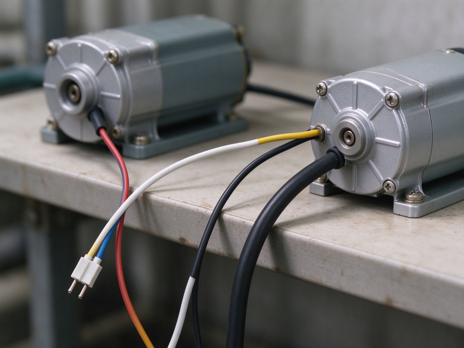
Beyond the pump itself, the voltage choice affects a few system details. The power supply must be rated for the pump current plus margin, the wires must avoid excessive voltage drop, and the control electronics must share the same rail or be isolated. A good design checks the voltage at the pump terminals under load, not just at the supply, because a long undersized wire can starve a 12V pump even when the supply reads 12V.
This is a measurement point: run the pump at its worst case and measure the voltage right at the motor terminals. If it sags well below the rated voltage, the wires or supply are too small. The micro peristaltic pump and the small peristaltic pump are both offered in the common DC voltages, so the choice is made at order time rather than by changing hardware.
| Decision point | Pick 12V if | Pick 24V if |
|---|---|---|
| Power source | 12V battery or adapter exists | 24V industrial rail exists |
| Cable length | Short, low-current | Long runs, high power |
| Duty cycle | Intermittent, portable | Continuous, panel-mounted |
| Wire and supply cost | Accept thicker wiring | Prefer thinner wiring |
| Existing control voltage | 12V logic | 24V PLC / sensor bus |
Voltage Sag and Cable Sizing
Once the pump runs, the current draw is not the only concern; it is the voltage the motor actually sees. Any resistance in the cable, connectors, and contacts drops voltage under load, and the motor sees the difference. This matters more on 12V because the current is higher, so the same cable resistance causes a bigger voltage drop. A 12V pump at the end of a long thin wire can run slowly, dose less, and even stall on startup, even though the supply at the other end reads a steady 12V.
The fix is to size the wire for the current and the length, and to keep connections clean. As a rule, shorter, thicker wires are the cheapest reliability upgrade on a 12V pump. On a 24V system the same drop is half as harmful because the current is half, which is why industrial panels tolerate longer runs on 24V. Measuring the voltage right at the pump terminals under running load is the check that confirms the wiring is adequate; this kind of controlled, point-of-load measurement follows the approach described by NIST’s Physical Measurement Laboratory, where the measurement is taken at the point of use rather than assumed from the supply.
Battery Life and Power Budget
In a battery-powered device, the voltage choice interacts with runtime. A 12V pump from a 12V battery uses the battery directly. A 24V pump in a 12V system would need a boost converter, which wastes some power and adds a failure point. Conversely, a 12V pump drawing high current from a small battery causes voltage sag that can confuse the device’s own electronics. The power budget should be written out: pump current plus duty cycle times run time, and the battery must support the peak current as well as the average.
Efficiency tilts toward 24V and BLDC for long battery or supply life, because less current means less waste in the wires and supply. But if the device already runs on 12V, forcing 24V through a converter usually loses the advantage. Match the pump to the rail, and let the motor efficiency, not the converter, do the work. Drivers that accept a defined speed-control input make the power behavior predictable, so the pump draws a steady current rather than spiking on startup.
Common Mistakes
The most common mistake is choosing 12V because it feels simpler, then undersizing the wires and supply. The second is specifying a 24V pump into a 12V device and adding a boost converter that costs more and fails sooner than a correctly matched pump. Match the pump to the rail, size the wires for the actual current, and measure the voltage under load before locking the design. A third mistake is ignoring the inrush: a motor starting against a sealed tube draws a brief peak current, and the supply and wires must survive that peak, not just the running current. A supply rated only for the running current can brown out on every start, which slows the first dose and confuses the controller.
If you are unsure whether 12V or 24V fits your instrument, tell YOORAIN the existing supply voltage, the pump power, the cable length, and the duty cycle. We can confirm the right voltage, the recommended wire gauge, and a matched driver, and send a sample so you can measure the real voltage at the motor terminals before production. That one measurement removes most of the guesswork, and it costs only a bench run.