
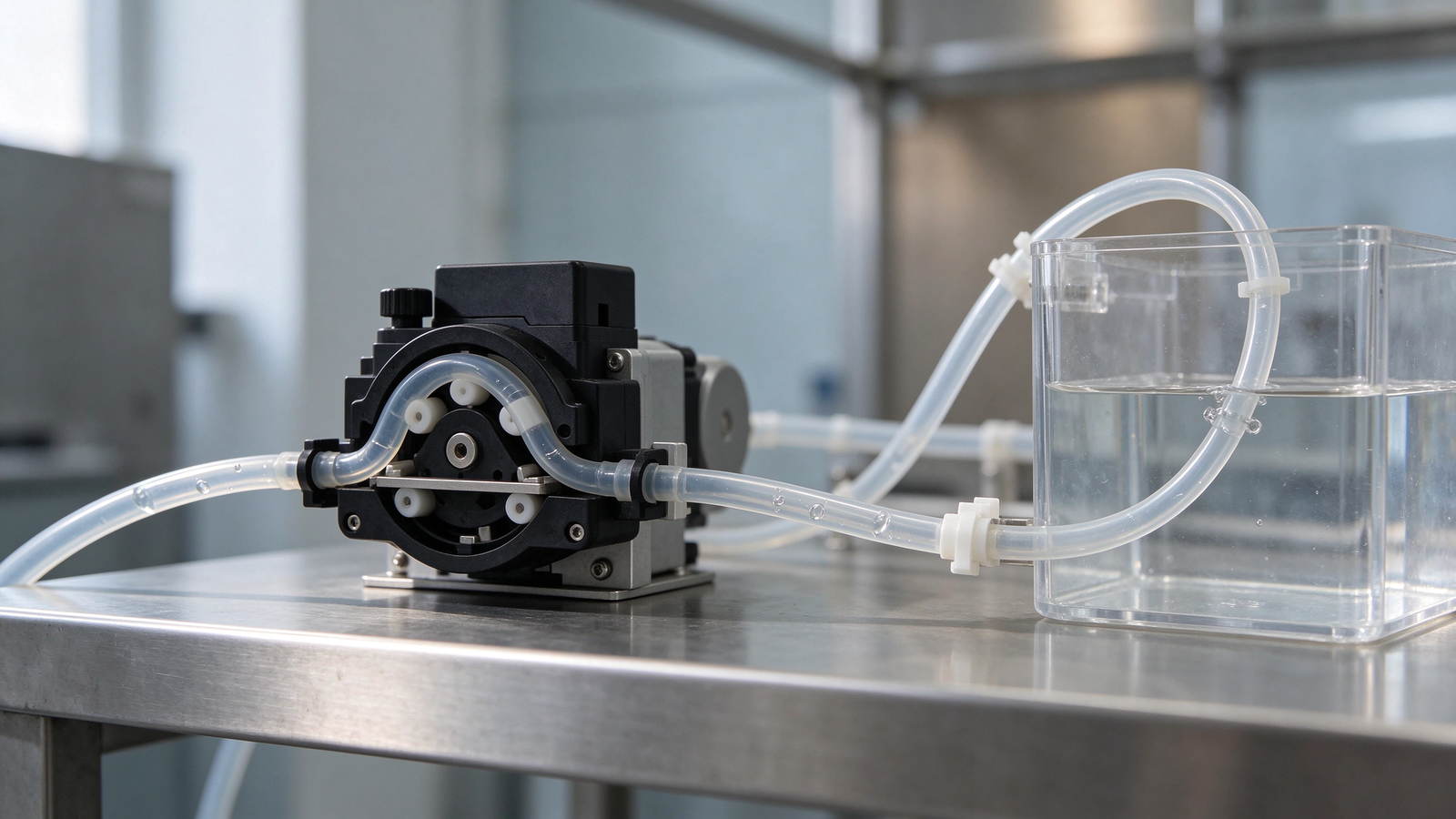
A peristaltic pump that delivers a steady dose one hour and a weak, sputtering, or intermittent flow the next is often suspected of wearing out its tube or losing drive speed. In a large share of these call-outs the cause is not the head or the motor but gas in the suction line: entrained air, a trapped pocket, vapor released from a warm or volatile fluid, or air drawn through a leaking inlet joint. Because a peristaltic pump draws fluid by creating suction behind the recovering tube, any gas that reaches the bore compresses and expands with each roller pass instead of moving as a liquid charge, and the delivered flow becomes uneven or drops away. This troubleshooting guide walks through what air binding looks like, where the gas comes from, how to trace it to its source, the layout and maintenance changes that remove it, and how to tell gas in the line apart from tube wear, occlusion, suction lift, or a leak on the discharge side.
What Air Binding and Intermittent Flow Look Like
Gas in a peristaltic suction line shows up in patterns that operators learn to recognize. The flow may pulse or spit at the outlet, the delivered volume drifts down between readings, the dose to a tank or analyzer varies from one cycle to the next, or the pump runs but barely moves liquid. In mild cases the pump recovers after a short run as gas is swept out; in worse cases the head fills with enough gas that the tube only compresses the pocket and no liquid reaches the outlet, which can be mistaken for a dead prime.
The useful distinction here is between a pump that never primes and one that primes and then loses a steady charge. Air binding tends to appear after the line has been running, after a tank refill, after the fluid warms up, or when the level in the source tank changes. A head that will not draw liquid from the start points more often to a suction lift that is too high, a collapsed or kinked inlet, or a tube that has lost its spring. A head that draws liquid but then sputters points toward gas entering or forming on the suction side.
Where the Gas Comes From
Gas reaches the peristaltic head through several routes, and each leaves a different clue in the installation.
Air drawn through a leaking inlet. The suction side of the head sits below atmospheric pressure, so any loose fitting, porous hose, cracked connector, or worn seal on the inlet can pull air in even when the discharge side shows no leak. This is the most common source on installed equipment that worked when new and began to draw air after the tubing aged or a fitting was loosened during service.
Entrained gas carried in the source fluid. Reagents that have been agitated, aerated during mixing, or held in a tank with a large headspace can carry fine bubbles into the suction line. Cool fluid that warms in the line releases dissolved gas; a volatile or low-boiling fluid can flash vapor under the reduced pressure at the pump inlet. In these cases the gas is generated by the fluid itself rather than by an external leak.
Trapped pockets in the line layout. A suction run that rises and falls, loops above the tank liquid level, or passes through a high point can hold a pocket that the pump does not sweep out. The pocket sits at the high point, and each roller pass only moves fluid past it partly, so the flow never settles to a steady charge.
Gas drawn back after shutdown. When the pump stops, fluid can drain back toward the tank and leave the inlet line open to the headspace, letting air sit in the line until the next start. A non-return or foot valve on the suction side holds the prime and keeps the line flooded between cycles where the duty needs it.
Symptom-to-Source Guide
| Observed symptom | Most likely source | First place to check |
|---|---|---|
| Flow sputters or spits at the outlet, then partly recovers | Gas pocket or entrained bubbles in the suction line | High points and loops in the inlet run; bubbles in the visible line |
| Flow was steady after install, became intermittent after service or hose aging | Air ingress through a loose or porous inlet joint | All suction-side fittings, connectors and the inlet hose for cracks or porosity |
| Problem appears after the fluid warms or after tank mixing | Gas released from the fluid under heat or agitation | Fluid temperature, tank headspace, and whether the fluid foams or aerates |
| Pump draws liquid at start, weakens as the run continues | Trapped pocket not being swept out, or suction lift rising as tank level drops | Line high points, tank level relative to the head, inlet bore |
| Line empties between cycles; first start of each batch is weak | Back-drain after shutdown drawing air into the inlet | Whether a foot or non-return valve is fitted and holding the prime |
| Flow drops steadily over weeks, no bubbles visible | Tube wear, fatigue or occlusion rather than gas | Tube condition, roller track, and delivered volume against a timed catch |
How the Peristaltic Head Handles Gas
A peristaltic pump moves fluid by occluding the tube with rollers and letting the tube spring back to its round bore, which draws the next charge into the head. Liquid is nearly incompressible, so each occlusion displaces a fixed charge toward the outlet. Gas compresses readily: when a bubble reaches the bore, the roller first squeezes the gas down, and the tube recovery partly re-expands the pocket instead of pulling a full liquid charge. The result is uneven outlet flow and a reduced delivered volume, even though the motor and rotor are turning at the set speed.
This behavior also explains why gas troubles are easier to see on small and metering heads. Compact heads such as those on a micro peristaltic pump and on a small peristaltic pump handle low volumes where a single bubble is a large fraction of the charge, so entrained gas shows up as dosing scatter rather than a mild flow reduction. A dosing arrangement such as the C300V24 dosing pump used on analyzer or reagent feeds should be checked with the inlet line visible, so gas can be watched moving toward the head rather than inferred from the outlet reading alone.
The peristaltic pump driver sets rotor speed and carries the torque for occlusion; it does not remove gas from the line. Raising the speed to push bubbles through faster can sometimes sweep a small pocket, but it also increases tube fatigue and does not fix an inlet that keeps drawing air. The fix belongs to the suction layout, the fluid condition, and the consumable condition, not to the drive setting alone.
Step-by-Step Diagnosis
Work from the inlet backward to the source tank, because air enters on the suction side and gas pockets form in the inlet run. Tightening the wrong side or replacing a sound tube first delays the real cause.
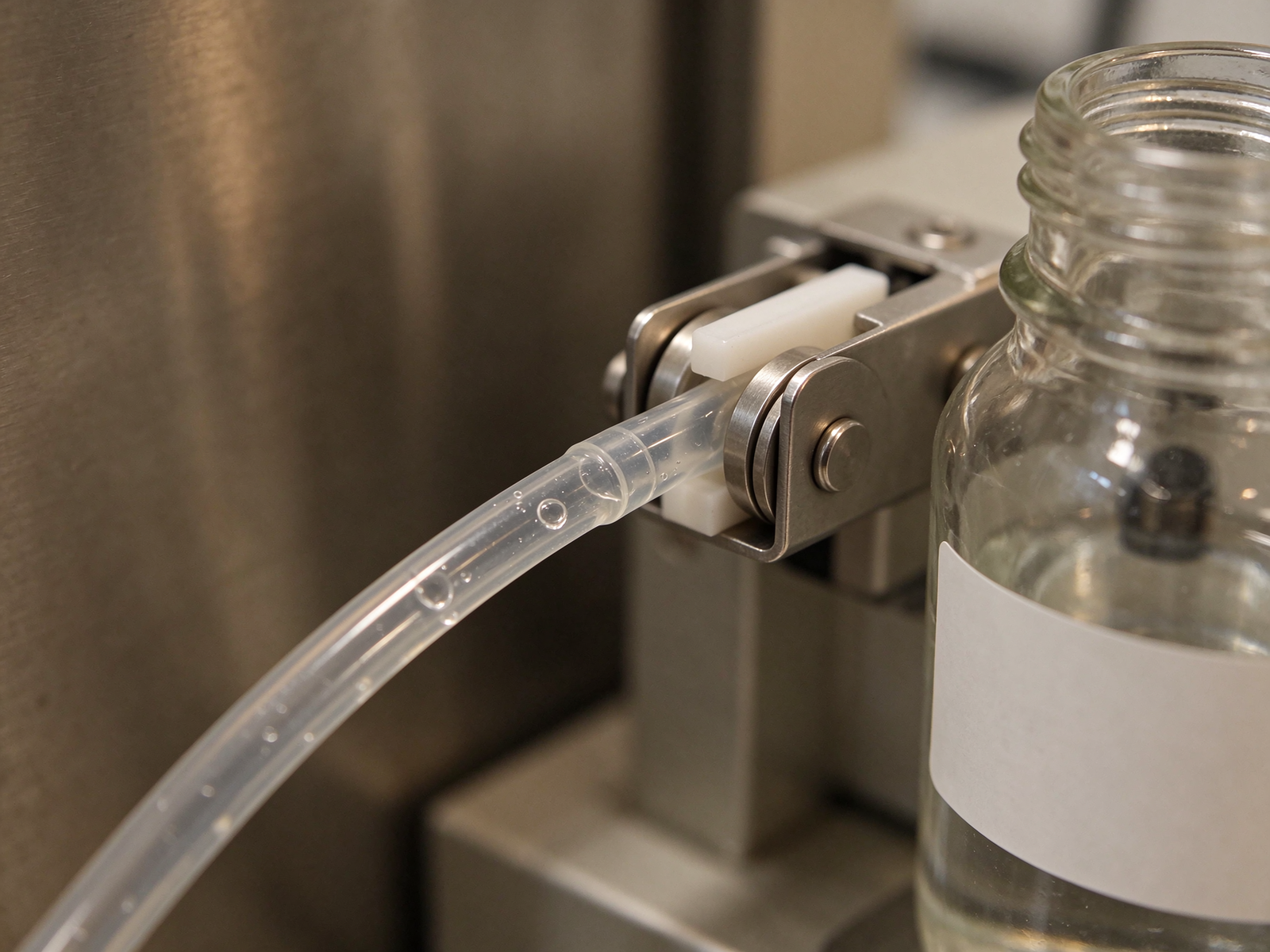
1. Watch the visible suction line. Run the pump with the inlet hose exposed where possible and look for bubbles traveling toward the head, a clear pocket at a high point, or a milky line that shows entrained gas. Bubbles forming in the hose rather than entering from the tank indicate a leak; bubbles already in the line from the source indicate entrained or released gas.
2. Isolate the inlet connections. Check every fitting, barb, compression fitting, and connector on the suction side for a loose fit, cracked part, or hose that has hardened and no longer seals on the barb. A porous or aged peristaltic pump tube can also admit gas, so compare the inlet consumable against its age and the fluid it carries.
3. Review the tank and fluid condition. Note the liquid level, whether the suction pick-up sits below the liquid surface without drawing in headspace, whether the fluid foams or aerates during mixing, and whether it warms enough to release gas. A tank that has been recently agitated may carry foam that the pick-up draws into the line.
4. Check the line routing for high points. Follow the inlet from tank to head and mark any rise above the tank liquid level, loop, or bend that can hold a pocket. The suction run should fall toward the pump or stay below the liquid level, with no trapped high point between source and head.
5. Confirm the prime holds between stops. Let the pump stop and watch whether the inlet line stays filled. If it drains back, the arrangement lacks a holding valve and air enters after shutdown; this shows up as a weak first dose on the next cycle.
Suction-Side Air-Entry Checklist
| Check point | What to look for | Corrective direction |
|---|---|---|
| Inlet fittings and barbs | Loose connections, cracked connectors, hose slipping off the barb | Seat and secure each joint; replace cracked fittings; use clamps where the duty calls for them |
| Inlet hose condition | Hardened, cracked, porous, or chemically attacked tube | Replace with a consumable compatible with the fluid and temperature |
| Suction line routing | High points, loops, dips that trap gas; long narrow run | Rerun the inlet short and direct, below liquid level, without trapped pockets |
| Pick-up position in tank | Pick-up drawing near the surface, foam, or headspace | Place the pick-up below the liquid surface, away from foam and the filling stream |
| Prime retention | Line drains back after the pump stops | Fit a foot or non-return valve on the suction side where holding the prime is required |
| Fluid condition | Aerated, foaming, warm, or volatile fluid releasing gas | Allow mixing to settle, review temperature, or use a flooded inlet where the fluid releases gas readily |
Layout and Maintenance Remedies
Once the source is identified, the remedy follows from it. A leaking joint is resealed or replaced; a trapped high point is rerouted; an aerated fluid is allowed to settle or fed from a flooded inlet; a line that drains back gets a holding valve. Where the fluid itself releases gas under suction, raising the inlet pressure by sitting the head below the tank level reduces the vacuum at the bore and lowers the chance of vapor forming, which is the same principle that governs flooded-inlet arrangements in other transfer duties.
| Identified source | Remedy | Notes to verify after the change |
|---|---|---|
| Leaking inlet fitting or porous hose | Reseal joints; replace the aged or incompatible consumable | Run a timed catch and compare delivered volume before and after; watch the line for bubbles |
| Trapped pocket at a high point | Reroute the suction run to remove the high point; keep the line flooded | Check that no loop remains above the tank liquid level after pipework is secured |
| Entrained gas from mixing or foam | Let the fluid settle before feeding; reposition the pick-up below foam | Observe whether the line stays clear after mixing and between tank fills |
| Vapor released under heat or low pressure | Use a flooded inlet or shorter lift; review fluid temperature at the pump | Confirm gas no longer appears when the fluid reaches its operating temperature |
| Back-drain after shutdown | Install a foot or non-return valve sized to pass the fluid | Verify the valve holds the prime and does not restrict the inlet or trap its own pocket |
Separating Air Binding From Other Causes
Before replacing parts, rule out the other failure modes that overlap with weak or uneven flow. Tube wear shows as a gradual loss of delivered volume over weeks, with no visible bubbles in the line; inspect the consumable for flattening, cracking, or a track where the rollers have occluded it. Occlusion that is too tight increases drive load and can age the tube quickly, but it does not produce bubbles. Excessive suction lift pulls the bore partly shut and reduces fill; this tracks tank level and improves when the head moves closer to or below the liquid. A discharge-side leak or restricted outlet affects the pressure the tube holds but does not put gas into the inlet, which is why tracing the inlet first keeps the diagnosis from wandering.
For dosing duties where the delivered volume has to be repeatable, measure output with a timed catch in a graduated measure rather than relying on the motor speed reading. A timed catch shows whether the charge per rotation has dropped, and watching the inlet line during that catch shows whether gas is present. Measurement practice for volume and level follows established metering guidance such as the practice material available from the NIST Physical Measurement Laboratory; consistent units and a clean, level measure matter when comparing one day’s dose against another. Engineering and materials research relevant to pump and fluid handling is summarized in programs listed by the U.S. National Science Foundation, and drive and occlusion behavior can be checked against the operating guidance in manufacturer reference documents such as the peristaltic pump driver reference and the motor-driver operating manual.
Prevention and Service Routine
Most air-binding calls are prevented by keeping the suction side simple and inspecting the inlet during each service. At service, check the inlet hose for aging, confirm fittings remain sealed, verify the pick-up stays below the liquid surface, and note whether the line holds its prime between cycles. Keep the inlet run free of high points when surrounding equipment is moved or added, since a rerouted process line can introduce a pocket that was not there during commissioning. Replace consumables on a schedule tied to the fluid and duty rather than waiting for output to drop, so a worn tube does not compound a gas problem.
Frequently Asked Questions
Will running the pump faster push the bubbles through? A small pocket may be swept out at higher rotor speed, but speed does not stop air from entering a leaking inlet or remove a trapped high point. Fixing the source keeps the flow steady without overspeeding the head and shortening tube life.
Why does the problem appear only after a tank refill? Refilling agitates the fluid and can leave bubbles or foam near the pick-up; the new liquid may also be warmer or cooler than the settled batch. Watch whether the gas clears after the tank settles, and whether the pick-up draws in the fresh filling stream.
Can a peristaltic pump pump gas? The head will pass some gas along with liquid, but gas compresses in the bore, so a stream that is mostly gas will not deliver a liquid dose like a filled line. The reliable answer is to keep the suction line flooded and free of pockets rather than rely on the head to handle an aerated stream.
Should a foot valve be fitted on every suction line? A foot or non-return valve helps where the pump sits above the source tank or cycles on and off and needs the prime held between stops. Where the head runs flooded and continuously, a valve may add an unnecessary restriction, so it should be matched to the actual duty.
Talk to the Pump Supplier Before Reworking the Inlet
If the intermittent flow persists after the inlet joints, routing, fluid condition, and consumable have been checked, share the details that decide the fix: the fluid and its concentration, working temperature, whether it foams or releases gas, the suction lift or flooded-inlet arrangement, the target flow and duty cycle, and the current head and tube bore. The supplier can then advise whether the arrangement needs a revised inlet, a different consumable material, or a head matched to the gas-prone duty.