
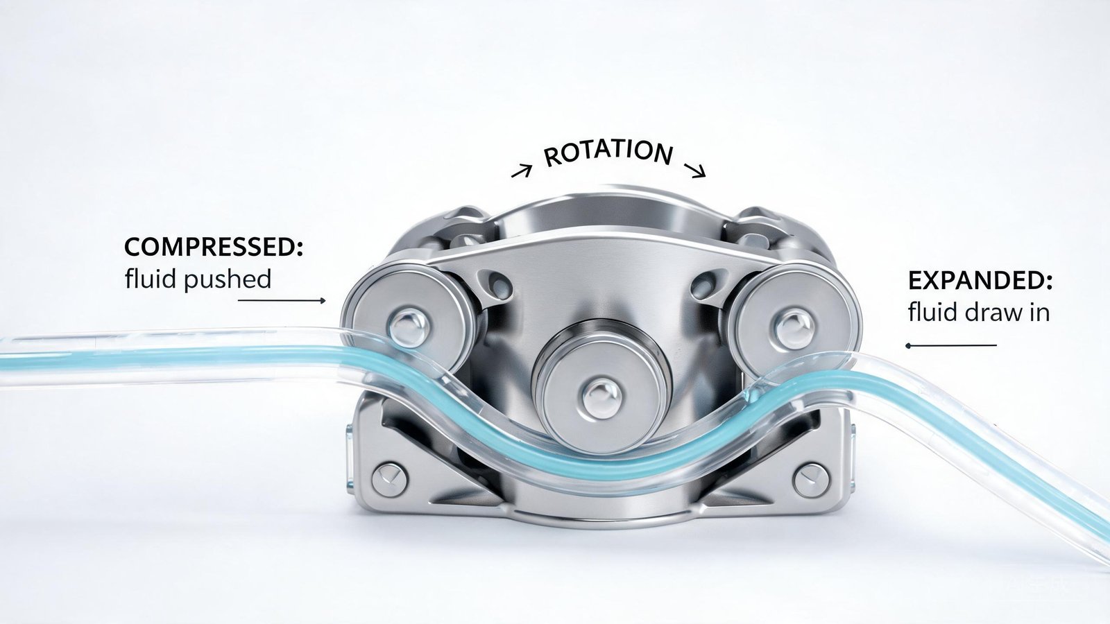
Engineers integrating peristaltic pumps into dosing systems, analytical instruments, and process equipment often encounter a predictable problem: flow pulsation. The cyclical compression and release of tubing by pump rollers produces an inherently non-continuous flow pattern. For applications requiring precise reagent dispensing or chemical dosing, even moderate pulsation can compromise measurement accuracy and pressure sensor readings. Understanding the causes of peristaltic pump pulsation — and the engineering options to reduce it — helps equipment designers select the right pump configuration for stable fluid delivery.
What Causes Pulsation in Peristaltic Pumps
Peristaltic pump pulsation originates from the fundamental operating principle of the pump. As rollers rotate around the pump head, each roller compresses the tubing to create a sealed “pillow” of fluid, then pushes that fluid forward. When the roller releases the tubing, the tubing rebounds and creates a momentary “void” — a brief reduction in flow. This alternating pillow-and-void cycle repeats with every roller pass, producing a pulsatile flow pattern.
Several design and operating variables influence the magnitude of these flow pulses:
- Number of rollers: Pump heads with two rollers produce larger individual pulses because the time between roller passes is longer. Heads with more rollers — six or eight — generate smaller, more frequent pulses, reducing the amplitude of each pulse.
- Roller occlusion pattern: In standard two- or three-roller heads, maximum occlusion occurs at top dead center (TDC). Multi-roller heads can be designed with offset occlusion, where the point of maximum compression is rotated away from TDC. This design difference affects how flow pulses overlap and combine.
- Tubing material and elasticity: Softer tubing materials such as silicone absorb more pulsation energy through elastic deformation. Harder tubing transmits sharper pressure spikes into the discharge line.
- Pump speed: Higher rotational speeds increase pulse frequency but can also change the amplitude characteristics depending on system resonance.
- Discharge line configuration: Short, rigid discharge lines transmit pulsation more directly to the point of use. Longer, flexible discharge tubing provides passive dampening through friction and elastic absorption.
The relationship between these factors is not always linear. For instance, a high-flow pump head with PPS construction and SUS304 rollers may produce different pulsation characteristics compared to a smaller pump head, even at equivalent flow rates, because of differences in roller count, tube occlusion, and rotor dynamics.
| Contributing Factor | Effect on Pulsation | Engineering Relevance |
|---|---|---|
| Roller count (2 rollers) | High amplitude, low frequency pulses | Larger flow variation per cycle |
| Roller count (6–8 rollers) | Low amplitude, high frequency pulses | Smoother flow delivery |
| Offset occlusion design | Pillow and void volumes partially cancel | Reduces net pulsation amplitude |
| Hard tubing material | Sharper pressure spikes | Less energy absorption at discharge |
| High pump speed | Higher pulse frequency | May interact with system resonance |
| Short rigid discharge line | Minimal passive dampening | Pulsation reaches point of use |
How to Diagnose Pulsation Issues
Before implementing fixes, confirm that flow instability originates from pump-generated pulsation rather than other system factors. Several diagnostic approaches help isolate the source.
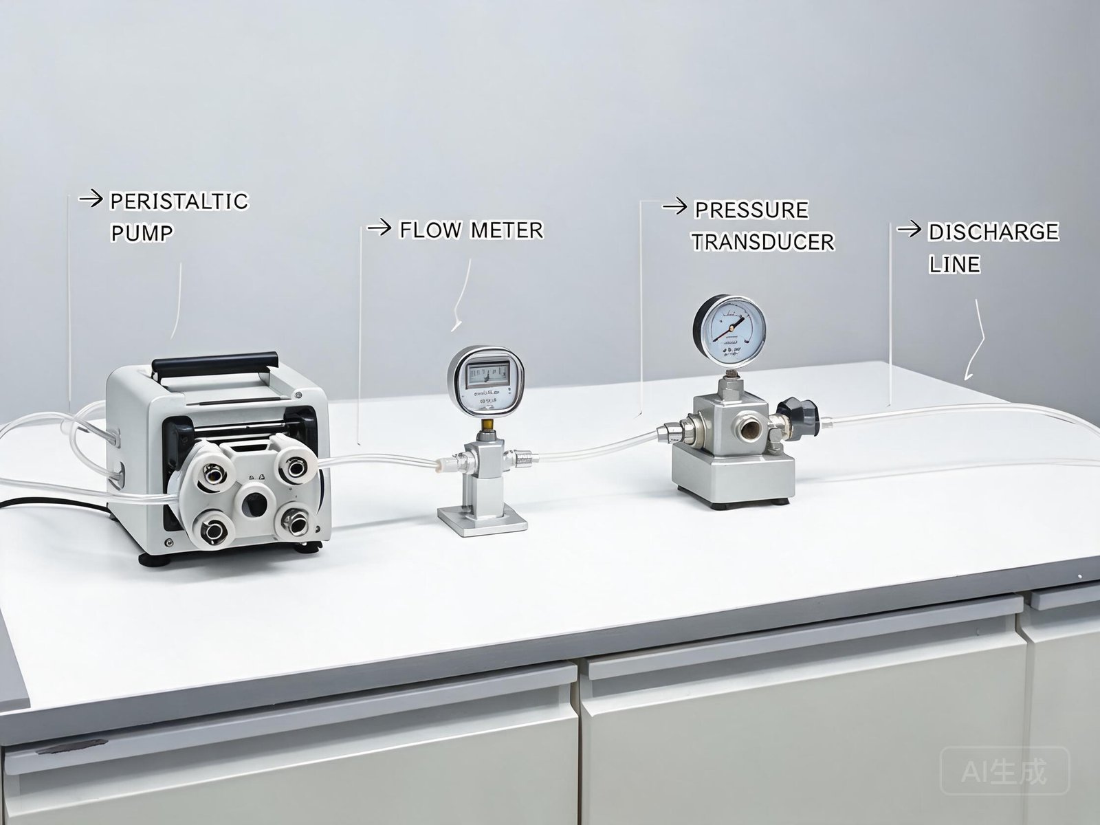
Visual observation: Fluctuating flow at the discharge point — visible in a graduated cylinder or transparent tubing — is the simplest indicator. If discharge flow visibly surges and recedes rhythmically in sync with pump rotation, the pulsation is pump-generated.
Pressure measurement: Installing a pressure transducer in the discharge line provides quantitative data on pressure ripple amplitude. The transducer should be placed close to the pump outlet to capture the full pulsation profile before system dampening attenuates it. Flow measurement standards maintained by the NIST Fluid Metrology Group provide reference points for calibration accuracy when measuring flow variation.
Flow meter monitoring: A coriolis or turbine flow meter in the discharge line reveals flow rate variation over time. Comparing the flow profile at different pump speeds helps distinguish pump-generated pulsation from system-induced fluctuations such as valve chatter or cavitation.
Tubing inspection: If pulsation has increased gradually over time, tubing fatigue is a likely contributor. Inspect the tubing inside the pump head for flattening, cracking, or loss of roundness. Tubing that has lost its elastic recovery produces less consistent occlusion, which amplifies flow variation.
Research published in ACS Omega confirmed that pulse amplitude and frequency depend on roller geometry, tubing condition, and pump head configuration — not solely on pump speed. This peer-reviewed study provides experimental data on how pump parameters interact to produce measurable flow ripple.
| Diagnostic Method | What It Reveals | Equipment Needed |
|---|---|---|
| Visual discharge observation | Gross flow variation pattern | Graduated cylinder, transparent tubing |
| Pressure transducer logging | Quantitative pressure ripple amplitude and frequency | Pressure transducer, data acquisition |
| Flow meter profiling | Flow rate variation over time at set speeds | Coriolis or turbine flow meter |
| Tubing condition inspection | Tubing fatigue, deformation, loss of elasticity | Visual inspection, caliper measurement |
Engineering Solutions for Reducing Pulsation
Once the source and characteristics of pulsation are understood, several engineering approaches can reduce its effect on the application. The choice depends on the required flow stability, available space, budget, and whether the system is a new design or a retrofit.
Pulse dampeners: A pulse dampener installed in the discharge line is one of the most effective solutions. The dampener contains a trapped air pocket above the fluid. As pulsating fluid enters the dampener, the compressible air absorbs pressure spikes — reducing pulsation by up to 90 percent in some configurations. Dampeners can be fabricated for most tubing sizes using a retaining vessel and appropriately sized fittings, as described in technical guidance from Avantor Sciences on peristaltic pump pulsation reduction. The fluid inlet and outlet should be positioned near the bottom of the vessel to maintain the air pocket at the top.
Multi-roller pump heads: Selecting a pump head with more rollers directly reduces pulse amplitude. For applications where flow stability is critical, a pump head with six or eight rollers produces smaller, more frequent pulses that are easier for downstream components to absorb. The K45 large flow pump uses engineering plastic rollers and wear-resistant bearings designed for smooth fluid transmission, which can contribute to more consistent flow delivery at higher rates.
Offset occlusion with dual pump heads: Mounting two pump heads with offset points of maximum occlusion — so their rollers do not reach TDC simultaneously — causes the pillow from one channel to partially fill the void from the other. When the inlet and outlet of each channel are joined with Y-connectors, pulsation can be reduced by 80 to 95 percent depending on the pump head design. This approach is particularly effective for flow rates up to approximately 460 ml/min.
Softer and longer discharge tubing: Selecting a softer tubing material such as silicone for the discharge line, and increasing its length, provides passive dampening. The elastic tubing absorbs pulsation energy, and the longer path increases friction that compresses individual pulses together. This method can reduce pulsation by up to 60 percent without additional hardware. Silicone pump tubing is available in various sizes compatible with different pump head configurations.
Variable speed control: For stepper motor-driven pumps, microstepping can smooth the rotational motion and reduce the sharpness of each roller engagement. While this does not eliminate the fundamental pillow-void cycle, it can reduce the transient pressure spikes that occur at each roller transition. The K45 pump supports DC motor, AC motor, and stepper motor options, giving designers flexibility in speed control strategy.
For large-scale industrial applications such as water treatment or chemical dosing, a YD25 peristaltic hose pump delivering 400 to 1000 liters per hour at up to 1 MPa outlet pressure may be appropriate. At these flow rates, discharge-side dampening is particularly important to prevent pressure fluctuations from propagating through the process line. Technical requirements for reciprocating positive displacement pumps are defined in ISO 16330:2003, which provides a reference framework for evaluating pump system performance.
| Solution | Pulsation Reduction | Best Suited For |
|---|---|---|
| Pulse dampener (discharge line) | Up to 90% | Systems with space for a dampener vessel |
| Multi-roller pump head (6–8 rollers) | Moderate to significant | New designs where pump head can be specified |
| Dual heads with offset occlusion | 80–95% | Applications requiring near-pulseless flow |
| Softer, longer discharge tubing | Up to 60% | Low-cost retrofit, passive dampening |
| Variable speed / microstepping | Reduces transient spikes | Stepper motor-driven systems |
When to Change the Pump or Tubing
Tubing replacement is the first maintenance action when pulsation increases over time. As tubing undergoes repeated compression cycles, it loses elastic recovery, develops flat spots at roller contact points, and may develop internal surface wear. These changes reduce occlusion consistency and increase flow variation.
However, tubing replacement alone will not resolve pulsation if the pump head design or system configuration is the root cause. Consider replacing or upgrading the pump head when:
- The current pump head has only two rollers and the application requires higher flow stability
- Tubing is being replaced more frequently than expected, indicating that the pump head or roller design is causing excessive tubing wear
- The required flow rate has changed and the current pump head is operating outside its optimal range
- Pulsation persists after fresh tubing installation and discharge line optimization
For applications governed by current good manufacturing practice, consistent fluid delivery is a regulatory expectation. 21 CFR Part 211 establishes requirements for equipment used in finished pharmaceutical manufacturing, where flow consistency directly affects product quality and batch reproducibility.
When evaluating replacement options, the peristaltic hose pump category offers configurations for continuous industrial operation, while smaller large-flow peristaltic pumps may be more appropriate for OEM instrument integration where space is constrained.
Engineering Checklist for Flow Stability
Use this checklist to evaluate and maintain peristaltic pump flow stability in your system:
- Roller count and design: Confirm that the pump head has sufficient rollers for the application’s flow stability requirement. Two-roller heads are acceptable for transfer tasks; six- or eight-roller heads or offset occlusion configurations are preferable for dosing and dispensing.
- Tubing material and condition: Verify that the tubing material matches the fluid being pumped and provides adequate elasticity for pulsation absorption. Schedule regular tubing replacement based on operating hours and duty cycle.
- Pulse dampener installation: If flow stability requirements exceed what the pump head alone can provide, install a discharge-side pulse dampener with a trapped air pocket sized for the flow rate and tubing diameter.
- Discharge line specification: Use sufficiently long, flexible discharge tubing to provide passive dampening. Avoid short, rigid runs that transmit pulsation directly to sensitive components.
- Pump speed verification: Confirm that the operating speed is within the pump head’s recommended range. Excessive speed can increase tubing wear and alter pulsation characteristics in unpredictable ways.
- Flow consistency monitoring: For critical applications, install a flow meter or pressure transducer downstream to monitor pulsation amplitude over time and detect gradual tubing degradation before it affects process quality.
If your dosing or fluid transfer system requires stable flow output with controlled pulsation characteristics, contact YOORAIN with your target flow range, tubing size, fluid type, and pulsation tolerance. Discussing these parameters upfront helps identify whether a standard pump head configuration will meet your requirements or whether a multi-roller or offset occlusion design is needed.