
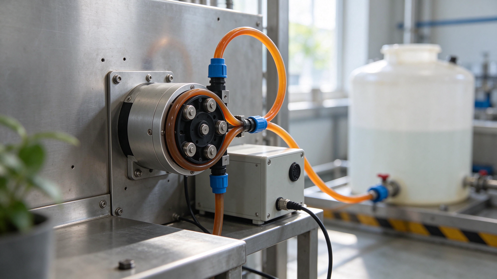
A peristaltic pump that fails to prime, delivers less than the target dose, runs hot, or ages the tube quickly is often blamed on the pump itself. In many cases the cause is set before the pump ever starts: how it is mounted, how the suction and outlet lines are routed, whether the lines carry stress onto the head, and whether the person servicing the unit can reach the tube. The same head and driver will perform differently on a well-supported, short, unrestricted arrangement than on a cramped installation where the inlet kinks, the outlet pulls sideways, or the tube cannot be changed without moving other equipment. This engineering guide walks through the installation and piping decisions that matter for a peristaltic tube pump, the checks to run before commissioning, and the common mistakes that show up as priming, output, or consumable-life problems later.
Why Installation Changes Peristaltic Performance
A peristaltic pump depends on the tube springing back to its round bore after each roller occlusion, and on that recovery drawing the next charge into the head. Anything that restricts inlet filling, adds unsupported weight or tension to the tube, or lets the head move under the stepping roller load works against that recovery. The pump does not rely on an impeller or an internal seal to pull fluid, so its suction behavior tracks the condition of the tube and the inlet line more directly than many other pump types. A long, narrow, kinked, or leaky inlet reduces the charge the bore can take; a rigid outlet pushed against the head puts side load on the housing; and a mounting surface that flexes lets the drive and head shift with each roller pass. Treating the installation as part of the pump selection, rather than an afterthought, prevents most of the repeat site calls that trace back to how the unit was set up.
Mounting Orientation and Securing the Head
The head and driver should sit on a flat, rigid surface that carries the weight without flexing. The mounting holes or bracket should be fastened securely so the stepping load from the rollers does not rock the unit; a loose or thin panel amplifies vibration, wears the mounting points, and can disturb alignment between the driver shaft and the head. Where the pump is built into a skid or machine frame, the mounting bracket should be sized to hold the head and drive arrangement rather than relying on the enclosure wall alone.
Orientation matters mainly for two reasons: service access and drain-back of fluid. The head should be positioned so the tube can be reached for inspection and replacement, and so no trapped pocket of chemistry sits where it can heat or age the tube between batches. In most arrangements the pump sits above the source tank for a suction lift, or below the tank for a flooded inlet; each changes how the inlet line is laid out. The peristaltic pump driver should have clearance around it for airflow, cable entry, and any manual adjustment, and the head should not be buried behind panels that cannot be removed quickly. Compact and small heads such as those on a small peristaltic pump are often built into instruments where panel space is tight, so the mounting layout should reserve service room before the surrounding enclosure is closed.
Suction Line Design
The inlet line is where most peristaltic installation problems appear. The tube inside the head can only draw what the inlet delivers, and a viscous or aerated fluid fills that bore more slowly than a clean water-like liquid. Keep the suction line short and as direct as possible, use a bore that matches the head and does not restrict filling, and avoid sharp bends, loops that can trap air, and fittings that narrow the path below the tube bore. Any connection on the suction side that leaks air breaks the prime, because the pump draws on suction rather than pushing fluid through a sealed primed line.
| Suction-side point | Good practice | What it prevents |
|---|---|---|
| Line length and routing | Short, direct run to the source; avoid long climbs or dips | Air pockets, slow fill, lost prime |
| Line bore | Matched to the head inlet; no narrow reducer on the suction side | Restricted fill and reduced delivered volume |
| Connections and fittings | Tight, sealed joints; no porous or aged inlet hose | Air ingress that prevents priming |
| Foot valve or strainer | Used where the duty needs hold-prime; sized to pass the fluid | Back-siphon after shutdown; blocked inlet |
| Liquid level relative to pump | Flooded inlet preferred where the tank sits above the head | Excessive suction lift and tube collapse |
| Tube condition at inlet | No kink, bend radius kept above the material minimum | Restricted bore and fatigue at the bend |
For lift duties, the allowable suction height depends on the fluid viscosity, temperature, vapor tendency, and the condition of the tube, so the inlet should be reviewed against the actual fluid rather than a generic lift figure. Warm or volatile fluids release gas more easily and need a flooded inlet or a shorter lift; thick fluids fill the bore slowly and reward a generous inlet run. If the source tank sits below the pump and the lift is high, the installation should be checked for tube collapse under vacuum before the duty runs continuously.
Outlet and Discharge Line Design
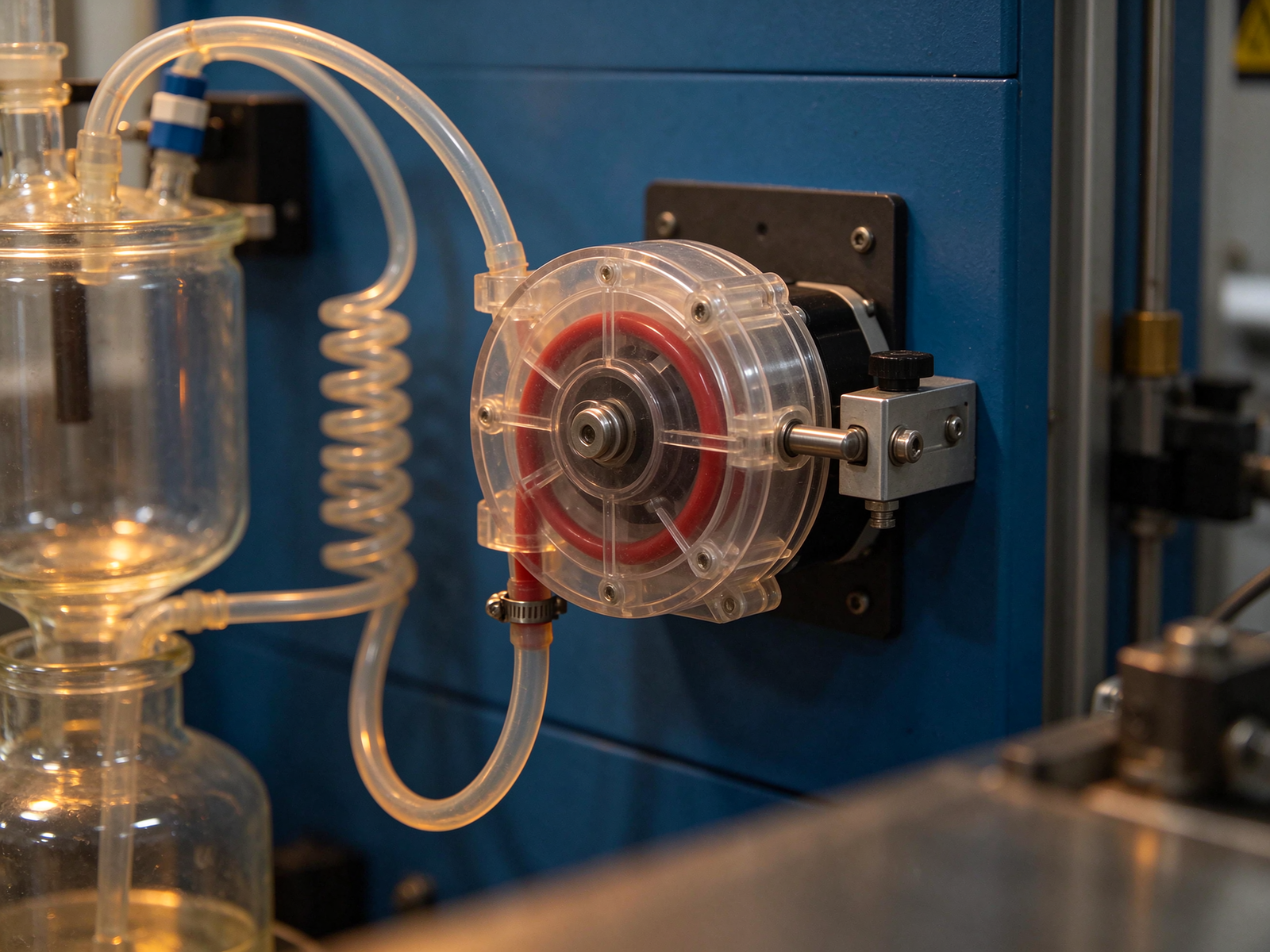
The discharge side carries whatever back-pressure the line and process impose on the tube. Long outlet runs, static head to a high tank, filters, valves, or restrictive fittings all add pressure that the occluded tube must hold. The outlet line should be laid out so it does not pull or push sideways on the head; rigid pipe connected directly to the fitting should have a flexible section or support that takes the weight off the pump port. A line that hangs off the fitting puts bending load on the tube end and housing, and can loosen the seal around the connection over time.
Where the discharge reaches a higher elevation or enters a pressurized line, account for the static head and any process back-pressure when the pump and tube are chosen. Excessive back-pressure opens slip inside the occluded tube, so the delivered volume drops even though the drive speed stays the same, and the tube bulges and ages faster. A pressure relief or back-pressure arrangement may be needed on duties where the line can close or rise steeply; that decision should be reviewed with the duty facts rather than added as an afterthought.
Line Support and Vibration Control
The roller action produces a stepping load that travels through the head into the mounting and the connected lines. Support the inlet and outlet so their weight rests on brackets, clips, or the pipework rather than on the pump fittings, and isolate rigid pipework from the head where vibration could transmit along the line. Leave a short flexible section between the pump port and any rigid run so movement at the head does not stress the connection. On skids, secure lines along the route so they do not sway or rub against other equipment, and check that no nearby panel or component touches the rotating parts.
Vibration that rises above the normal roller passage should be treated as a signal to check mounting tightness, tube seating, and drive alignment rather than accepted as normal noise. Loose mounting fasteners, a tube that sits unevenly in the head, or a drive and head that are not aligned properly all amplify the stepping load into a visible shake.
Ambient Conditions and Wash-Down Exposure
| Environment factor | Installation consideration | Check before commissioning |
|---|---|---|
| Ambient temperature | Heat around the drive softens the tube and ages the material; keep the head away from hot ducts | Measure the local air temperature and any radiant heat source |
| Wash-down or splashing | Match the enclosure and mounting to wet exposure; keep electrical entries oriented away from spray | Confirm the driver protection suits the cleaning method |
| Chemical fumes or spillage | Locate the head where drips do not collect on the tube or housing; ventilate close chemistry areas | Review fume compatibility with the tube and housing materials |
| Dust or particulate | Protect the drive and keep the head clear of accumulated debris that blocks airflow | Plan an exterior cover or enclosure suited to the environment |
| Power supply and cable routing | Run power and signal cables away from motor leads where interference matters; secure cables so they do not pull on terminals | Check voltage, cable gauge, and entry sealing for the drive |
Where the pump will be hosed down or exposed to spillage, the enclosure and fitting arrangement should match that exposure; an indoor bench unit and a wet-skid unit are not mounted or protected the same way. The motor-driver operating manual and peristaltic pump driver reference describe the drive-side mounting, wiring, and clearance practices that should be followed for the selected arrangement.
Service Access and Consumable Routine
The tube is the main consumable on a peristaltic, and the installation should make replacing it a straightforward task rather than a teardown. Leave enough room around the head to open the cover, remove the tube, fit a replacement, and route the new tube through the rollers without reaching around brackets or neighboring components. Keep the replacement bore and material in stock where the duty runs continuously, and record the installed tube material, bore, and fitting type so the next service uses the correct part. The peristaltic pump tube for a given head is selected against the fluid and chemistry, and service access matters as much as the material choice because a tube that cannot be reached for inspection is left in place past its condition.
Smaller heads used on reagent and instrument duties, such as the micro peristaltic pump range, are often mounted where consumable changes happen at scheduled intervals; the panel layout should still allow the cover to open and the fittings to be released. On higher-flow transfer duties served by a large-flow-rate peristaltic pump, the heavier head and line weights need a more substantial bracket and clear access around both ports.
Commissioning Checks Before the First Run
After mounting and piping, run through a short commissioning check before handing the unit to production. Confirm the head is fastened securely, the tube sits evenly in the housing without twist, the inlet and outlet connections are tight, and the inlet line is primed or ready to draw. Run the drive briefly and watch the rotation direction, listen for rubbing or uneven roller load, and check that no line pulls against the fitting. Measure the delivered volume against the target dose using a timed catch and weigh or volume check, so the installed arrangement can be compared against the duty requirement before the pump takes over a continuous batch. Measurement practice for delivered-volume checks follows the weighing and timing methods described by the NIST measurement practice, and fluid-handling background for process installation is available from NSF engineering research.
Common Installation Mistakes
| Mistake | Symptom it tends to cause | Correction |
|---|---|---|
| Long or restricted inlet line | Slow fill, weak prime, low delivered volume | Shorten the suction run, match the bore, remove kinks and reducers |
| Air-leaking suction joints | Loses prime after shutdown; intermittent output | Re-seal connections; replace aged or porous inlet hose |
| Rigid outlet pulled against the port | Side load on fitting, leak at connection, vibration | Add a flexible section and support the outlet run separately |
| Thin or flexing mounting surface | Rocking under roller load, noise, loose fasteners | Use a rigid bracket; secure head and driver to the frame |
| No service room around the head | Tube changes delayed; inspection skipped | Plan cover opening and fitting clearance before enclosure closure |
| Back-pressure not reviewed | Slip, reduced dose, bulging or fast-aged tube | Account for static head, filters and valves; check tube pressure limit |
| Drive mounted where heat or fumes collect | Tube softening, shortened consumable life, drive stress | Relocate away from heat and fumes; confirm enclosure exposure |
When the Installation Should Be Rechecked
An installation that worked at low flow can develop problems as the duty changes: a thicker fluid, a warmer batch, a higher discharge tank, or an added filter on the outlet all raise the load on the tube and inlet. If output drifts after a chemistry or recipe change, recheck the inlet condition, the outlet back-pressure, and the mounting before assuming the pump has worn out. After any tube change, confirm the new tube is seated evenly and the connections still seal, and re-measure the delivered volume so the commissioning baseline carries into service.
Frequently Asked Questions
Does the pump have to sit below the source tank? No. A flooded inlet (tank above the head) is the easier suction condition, but a correctly laid out inlet can draw a limited lift. The allowable lift depends on fluid viscosity, temperature, vapor tendency, and tube condition, so the inlet should be checked against the actual duty.
Can rigid pipe be connected straight to the pump port? Rigid pipe should not hang its weight or impose side load on the fitting. Use a short flexible section between the head and the rigid run, and support the rigid pipework on brackets.
How much space does a tube change need? Enough to open the head cover, release the fittings, remove the old tube, seat the new one, and re-route the line without moving neighboring equipment. This should be planned at the panel or skid layout stage rather than measured after the unit is installed.
What installation issue causes intermittent priming? Most often an air leak on the suction side, a kinked or collapsed inlet, or an inlet that traps an air pocket. Check joints, line bore, routing, and tube condition before looking at the drive.
Does mounting orientation affect the pump internals? The peristaltic head has no internal rotating seals to rely on orientation, but orientation affects drain-back, service access, and where spillage collects. Keep the head accessible and avoid trapping chemistry against the tube.
How is delivered volume verified after installation? Catch the output over a timed interval and measure volume or weight against the target dose, comparing the installed arrangement to the duty requirement. Re-check after a tube change or any change to the fluid or line.
If you are laying out a peristaltic installation for a dosing or transfer duty, send YOORAIN the fluid and concentration, working temperature, target flow, suction and discharge conditions, available mounting space, and the control arrangement. We can advise on the head size, tube material, driver, and line layout that fit the duty, and flag where the inlet or outlet design needs review before commissioning.