
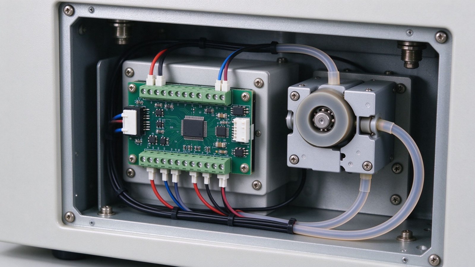
When an OEM instrument needs a controlled, repeatable flow, the pump itself is only half the design. The other half is how speed is set and held over the product’s life. A pump that runs at a fixed free-flow rate is usually not enough. An analyzer, a dosing module, or a filling station needs a pump whose speed follows a control signal, holds a setpoint despite supply-voltage variation, and reacts in a predictable way when the controller changes its mind. This article explains the speed-control interfaces that matter in OEM peristaltic pump design, how to think about turndown and feedback, and what to confirm before locking a pump configuration.
Why Speed Control Matters in OEM Fluid Systems
In a peristaltic pump, flow is roughly proportional to roller speed at a fixed tubing bore and fluid viscosity. That relationship is useful because it lets engineers set flow by setting speed. But the real-world relationship drifts as tubing compresses, as voltage sags, and as viscosity changes with temperature. A speed-control scheme that ignores those effects will drift with them.
For an OEM product, the control interface is part of the user experience. A medical or analytical instrument that asks the operator to type a volume expects the pump to deliver it consistently across units and over thousands of cycles. A dosing skid that receives a 4–20 mA signal from a PLC expects the pump to track that signal linearly. The choice of control architecture determines whether the instrument behaves like a calibrated product or like a bench prototype.
Common Control Signal Interfaces
OEM peristaltic pumps and their drivers expose a small set of standard control signals. Designers should pick the one that matches their controller and the resolution they need, rather than adopting the most expensive option by default.
| Interface | Typical range | Best fit | Notes |
|---|---|---|---|
| Fixed DC voltage | Fixed speed | Simple transfer, single-setpoint modules | Lowest cost; no external speed command. Drift follows line/voltage variation. |
| Analog voltage | 0–5 V or 0–10 V | PLC/analog output control, continuous dosing | Common on OEM drivers; resolution often limited to 8-bit steps per driver design. |
| Current loop | 4–20 mA | Industrial environments, long cable runs | Rejects loop voltage drops; preferred on factory-floor dosing. |
| PWM / frequency | 0–10 kHz style pulse train | MCU-controlled instruments, closed-loop setpoints | Speed follows pulse frequency; easy to generate from a microcontroller. |
| Digital / communication | RS-485, CAN, BCD dial | Multi-parameter instruments, setpoint menus | Allows direction, ramps, and counters beyond simple speed. |
Driver manufacturers commonly accept more than one of these on the same unit. A compact stepper-motor driver, for instance, exposes an analog speed input of 0–5 V DC with a defined step resolution, as documented in the stepper driver analog speed-control reference. Other OEM driver units list selectable inputs such as 4–20 mA, 0–5 V, 0–10 V, and pulse-frequency input, with the mapping between signal range and speed range configurable over communication commands, as described in a compact motor-driver operating manual. That flexibility is useful, but it also means the control wiring and the driver setup must be defined together during integration, not after the unit is mounted.
Flow Range and Turndown Considerations
The most important number for a speed-controlled pump is not the maximum flow but the usable turndown: the ratio between the maximum and the minimum flow the application can still deliver accurately. Peristaltic pumps can turn down well in theory, but at very low roller speed the pulse gap between rollers becomes a large fraction of each dispense, and tubing recovery time starts to matter.
A dosing application that spans a 50:1 flow range on paper often cannot hold repeatability across the whole range on one head. Engineers should define the minimum dispense and minimum steady flow the instrument must support, then ask whether the chosen pump head and tubing can hold that range without pulsing or stalling. Starting a peristaltic pump at slow to medium speed rather than jumping to full speed is standard practice to avoid stalls and to keep the rollers from binding on a cold, stiff tube.
| Design question | Why it matters |
|---|---|
| What is the minimum repeatable dispense volume? | Sets the lowest usable roller speed and required tubing recovery. |
| What is the turndown the controller expects? | Determines whether one head can cover the range or a second pump stage is needed. |
| How will the setpoint be scaled? | Analog/PWM mapping must match the expected flow, not the raw RPM. |
| What happens at signal loss? | Fail-safe behavior (stop, hold, or defined speed) should be decided in the controller. |
Open-Loop vs Closed-Loop Speed Control
An open-loop drive sets voltage or frequency and assumes the pump reaches the commanded speed. A closed-loop drive adds feedback, typically from an encoder or Hall sensor on the motor, and corrects speed against the setpoint. The trade-off is cost and complexity against accuracy under load and over temperature.
Open-loop control is acceptable when the flow range is modest, the voltage supply is well regulated, and the application tolerates a few percent of drift. Closed-loop control earns its cost when repeatable dosing across voltage tolerance, supply variation, and product life is a selling point of the instrument. For a micro pump inside an analyzer, closed-loop speed holding is often the difference between a one-point calibration that lasts and a pump that must be recalibrated every few weeks. The peristaltic pump driver used in the design should be matched to the motor type and to the feedback scheme chosen.
Electrical and Mechanical Integration
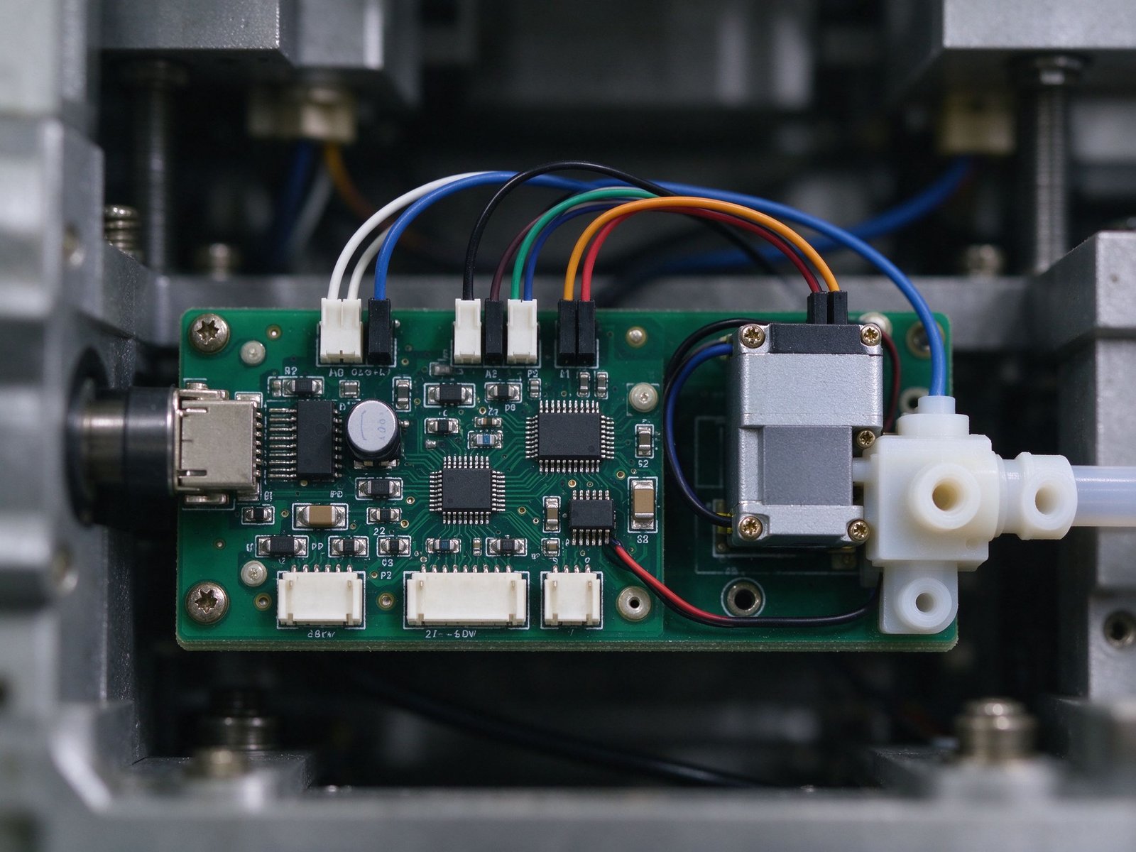
Speed control interacts with the rest of the instrument in ways that are easy to underestimate. The motor and driver generate heat and electrical noise; the pump head needs access for tube loading; and the control wiring must stay clear of the rotating rollers. For laboratory and measurement equipment, speed control also ties into the accuracy of the finished instrument, which is why measurement-science resources such as NIST, the U.S. National Institute of Standards and Technology, are the reference point when a product is claiming calibrated or traceable flow behavior.
Two integration details are worth checking early. First, motor heat affects the tube sitting in the head. A pump run at a high duty cycle warms the head, which softens the tubing and slightly changes the compression characteristic over a run. That is why a flow that is correct at warm-up can drift after an hour of continuous dosing; engineers should run the duty cycle on the bench before locking the speed setpoint. Second, the control signal and the motor leads should be routed away from each other and away from sensitive analog sensing lines, because the PWM or brush commutation noise can couple into nearby measurement circuits and disturb the very readings the instrument is producing.
Mechanically, a compact micro peristaltic pump or a mini peristaltic pump is often chosen when the mounting space is tight and the flow target is small. The control signal then has to reach a driver that may sit next to the pump or on the main instrument board. Confirm the driver’s supply voltage, the analog input impedance, and the wire gauge expected by the manufacturer before locking the enclosure layout. The peristaltic pump tube chosen for the application also affects how speed converts to flow, because a softer or harder tube changes the compression characteristic and the effective displacement per roller.
Engineering Checklist for OEM Pump Speed Control
Before releasing a speed-controlled peristaltic pump design, confirm the following with the supplier:
- The control interface (analog voltage, current loop, PWM, or digital) matches the controller output and the resolution required.
- The usable turndown covers the minimum dispense and minimum steady flow, not just the advertised maximum flow.
- The open-loop vs closed-loop choice matches the accuracy and drift requirements of the finished instrument.
- The driver supply voltage, analog input range, and wiring expectations are documented for production assembly.
- The tubing material and bore are known to convert the commanded speed into the expected flow within tolerance.
- Fail-safe behavior on signal loss is defined in the controller logic.
- Electrical integration has been checked against applicable equipment safety standards.
If you are designing an OEM instrument and need help selecting a pump and driver configuration, contact YOORAIN with your target flow range, the control signal your controller provides, and the mounting constraints of your equipment. Providing those details up front helps narrow the pump head, motor, and driver combination to a workable option rather than a generic recommendation.