
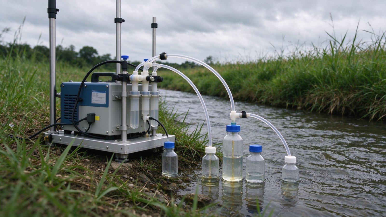
Environmental monitoring equipment collects water samples that are meant to represent a river, a wastewater discharge, a stormwater outfall, or a treatment-works outlet. Those samples feed chemical and biological analysis, so the fluid path between the sampling point and the sample bottle matters. Peristaltic pumps are a common choice in automatic samplers because the fluid only touches the inside of the tube, which simplifies cleaning and reduces cross-contamination between sites. This article looks at why peristaltic pumps fit water sampling, what fluid-handling requirements drive the selection, and the design problems that sampler manufacturers should plan for.
Why Peristaltic Pumps Fit Water Sampling
In an automatic sampler, a pump lifts sample water from a stream or a discharge point and delivers it to one or more sample bottles. A peristaltic pump suits this job for three practical reasons. First, the fluid path is limited to the tubing, so the only wetted component that contacts the sample is a replaceable tube. Second, the pump does not submerge a mechanical seal or impeller in the water, which reduces fouling from suspended solids. Third, the flow can be started, stopped, and reversed by controlling the roller head, which helps purge the line between samples.
EPA sampling procedures for stormwater and wastewater routinely describe automatic samplers built around a peristaltic pump, with intake tubing that is replaced or cleaned between sites. The U.S. EPA stormwater sampling method, for example, describes collecting grab samples with a peristaltic pump that is part of an automatic sampler, using clean intake tubing for each event. That pattern—sample touches only the tube, and the tube is controlled—is the core reason peristaltic pumps appear in environmental sampling hardware.
Main Fluid-Handling Requirements
Water sampling has requirements that are different from continuous dosing. The pump may sit idle for long periods, then draw a sample quickly. It must lift water from a stream or well, deliver a known volume, and not disturb volatile or fragile analytes. Established sampling guidance shapes what the pump and tubing must tolerate.
The U.S. EPA’s Handbook for Sampling and Sample Preservation of Water and Wastewater discusses automatic samplers and the factors that should drive unit selection, including variation in flow, suspended solids, and floating material. EPA field procedures for stormwater describe grab samples collected with a peristaltic pump built into an automatic sampler, with clean intake tubing used for each event. For regulated discharges, the U.S. EPA NPDES programme sets the sampling and monitoring framework under which such automatic samplers are commonly deployed.
| Requirement | What it means for the pump |
|---|---|
| Suction lift | Pump must lift sample from a stream, outfall, or sampling port without losing prime. |
| Sample volume accuracy | Discrete grab or composite aliquots must be repeatable across bottles and events. |
| Idle-to-start behavior | Long idle periods must not stiffen or degrade the tube so that the next draw fails. |
| Analyte preservation | Turbulence and aeration should be limited for volatile or oxygen-sensitive analytes. |
| Cleanability | Fluid path must be simple to flush, and tubing must be replaceable in the field. |
Pump Selection Considerations
Choosing a pump for a sampler starts with the sample volume and the suction lift, then moves to duty cycle and tubing. A sampler that collects a small number of discrete bottles per day places light intermittent duty on the pump. A flow-proportional composite sampler, which draws small aliquots throughout a discharge event, asks the pump to cycle repeatedly and to track a flow signal.
The pump head size and tube bore set the flow range. A micro peristaltic pump is often adequate for small-volume sampling modules where the goal is controlled small draws rather than high flow. A small peristaltic pump with a larger head can handle bigger sample volumes or longer suction lifts. The peristaltic pump tube material should be chosen for chemical compatibility with the water being sampled and for the expected number of compression cycles before replacement.
| Application | Typical pump duty | Key selection point |
|---|---|---|
| Discrete grab sampler | Short draws, idle between events | Reliable priming and simple tube loading. |
| Flow-proportional composite | Repeated small aliquots paced by flow | Repeatable small volume and control interface. |
| Stormwater event sampler | Irregular starts, possible solids in flow | Tubing durability and ability to purge the line. |
| Treatment-works outlet | Scheduled sampling, cleaner water | Steady flow and low maintenance. |
Common Design Problems
The recurring failures in field samplers are tied to suction, tubing condition, and aeration. If the intake line is too long or the pump cannot build enough lift, the sampler fails to prime and records a missed sample. If the tube is left compressed between events, it can develop a flat spot that reduces flow until it is replaced. If the pump runs too fast, it shears or aerates the sample, which is a problem for volatile organic or dissolved-oxygen measurements.
Suction performance depends on the pump’s ability to evacuate the intake line, the tube’s resistance to compression, and the vertical lift from the water surface to the pump head. Sampler designers should define the maximum lift the equipment must handle and test it with the chosen tubing, because a pump that primes on the bench may lose lift in cold weather when the tube is stiffer. Back-purging or reversing the rollers between samples is a practical way to clear the line and reduce carry-over. It also helps to keep the intake point fixed and submerged consistently, because drawing air into the tube spits air into the sample bottle and biases the aliquot volume.
Integration Into Equipment
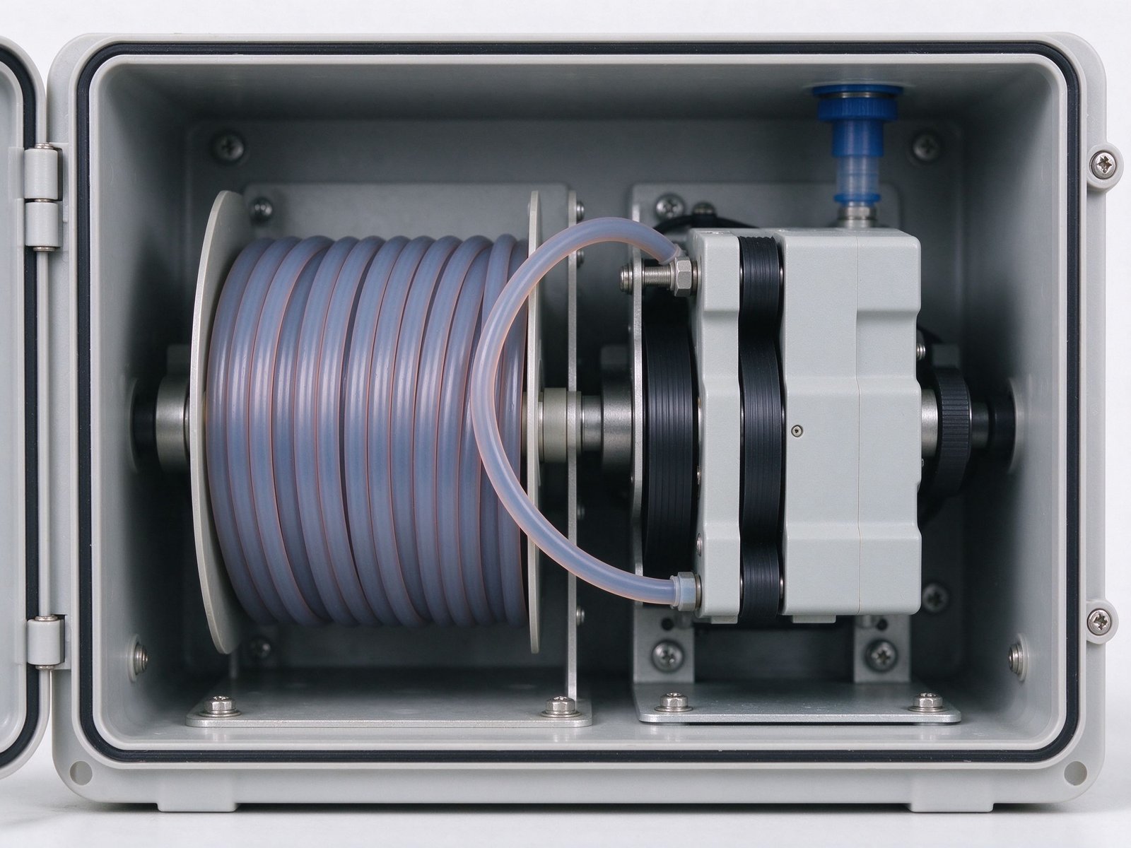
An OEM sampler integrates the pump with the bottle tray, the control board, and the intake fitting. The pump head should be mounted where the tube can be changed without tools, because field crews are the ones doing that. The control board must drive the pump for the right duration per aliquot and must log when a draw occurs, so that composite timing is traceable. Because samplers are deployed outdoors, the motor and driver should be rated for the expected temperature range and protected from moisture.
Two operating details separate a reliable sampler from a finicky one. The first is purge: after a draw, a short reverse run or a burst of clean water clears the intake line so the next aliquot is not contaminated by carry-over. The second is temperature. Cold weather stiffens the tube, which reduces the pump’s ability to prime and lift water; a sampler tested in a warm lab can lose suction in a freezing stream. Designers should specify the operating temperature range, confirm the chosen tube material still flexes at the low end, and build a priming routine that retries a draw if the first one does not deliver the expected volume.
When integrating, define the flow signal the sampler controller will produce—fixed speed, timed draws, or a paced composite—and confirm the pump driver supports it. Document the tube replacement interval and the priming procedure, because those are the items that determine whether the sampler keeps producing valid data after months in the field.
Key Takeaways
- Peristaltic pumps fit water sampling because the sample touches only a replaceable tube, which simplifies cleaning and reduces cross-contamination.
- Selection should start from suction lift and required sample volume, then move to duty cycle and tubing material.
- Flow-proportional composite samplers need repeatable small aliquots and a control interface that tracks a flow signal.
- Field failures usually trace to priming loss, degraded tubing, or over-fast draws that aerate the sample.
- Sampler design should follow applicable sampling and quality-assurance guidance, including ISO 5667 series and EPA sampling handbooks.
If you are developing environmental or water-monitoring equipment and want to discuss the fluid-handling requirements of your sampler, contact YOORAIN with your target sample volume, suction lift, and the control signal your sampler controller uses. Those details help narrow the pump head, tube, and driver combination to a configuration that works in the field rather than only on the bench.