
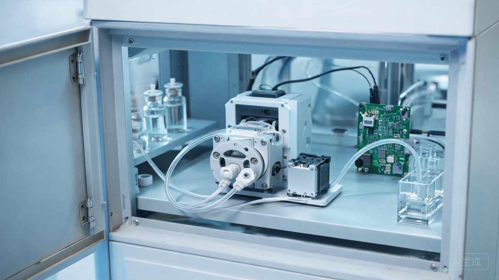
An online analyzer or an ink-jet delivery module with a drifting reagent dose rarely fails outright. It starts quietly: standard concentrations read slightly low, replicate aliquots spread wider than they did last quarter, and the calibration coefficient that used to sit at 0.98 now needs correcting every few weeks. The pump is often blamed for an electronics fault when the real cause sits in the tube, the operating point, or the calibration record. The K15 micro peristaltic pump is built for exactly these low-flow duties — its published maximum is 350 mL/min, with a design emphasis on accuracy, low noise and long tube life — but it only holds its stated performance when installed, tubed and calibrated the way its working principle demands.
This guide gives service and instrument-engineering teams a structured route from symptom to root cause for a K15 micro peristaltic pump dosing accuracy problem, a gravimetric recalibration procedure, and the decision criteria for changing the pump configuration instead of repeatedly correcting the same drift.
How the K15 Moves Fluid, and Where Accuracy Is Lost
The K15 is a positive-displacement tube pump: rollers on a rotor sequentially occlude a tube against the pump track, trapping a fluid packet between the contact points and moving it from inlet to outlet. Delivered volume per revolution is the product of the tube’s effective internal volume and the number of occlusion cycles. There are no seals in the fluid and no priming valve, which makes the pump tolerant of reagents and easy to clean by tube replacement. It also means that anything changing the tube’s internal geometry, or the number of revolutions actually completed, changes the dose.
Two K15 configurations directly shape the accuracy profile. The pump is offered with two rollers for longer tube life and four rollers for lower pulse. Two roller packs compress the tube fewer times per revolution, so the tube fatigues more slowly; four roller packs overlap the occlusions, shortening the time between packets and smoothing the instantaneous stream — useful when an optical detector or a narrow mixing chamber reacts to pulsation. The tube options are 14#, 16#, 25# and 17# in silicone or BPT.
Symptom-to-Cause Troubleshooting Table
| Observed symptom | Most likely cause | First check / action |
|---|---|---|
| Delivered volume slowly declines over weeks; controller coefficient creeps upward | Tube fatigue — the wall loses rebound and each stroke traps less fluid | Record run hours; replace the tube on schedule rather than after failure; re-calibrate with the same tube lot |
| Large jump in dose right after a tube change | Tube size or wall thickness differs from the replaced one; occlusion not seated | Verify the printed size (14#/16#/25#/17#) and material; reseat the tube fully into the track before closing the head |
| Readings vary with ambient or reagent temperature | Viscosity change and tube material stiffness change alter fill between rollers | Calibrate at operating temperature; insulate or temperature-control the reagent line if swings are large |
| Intermittent under-dose with bubbles in the suction line | Air entering on the inlet side, partial loss of prime, or a blocked inlet strainer | Inspect fittings, tube inlet depth and strainer; purge; keep suction run short and flooded |
| Dose correct at mid-speed, wrong at the slow or fast end | Operating outside the calibrated speed range; viscosity effects at low speed, occlusion losses at high speed | Recalibrate at the actual running speed or move the operating point toward the middle of the range |
| High reading scatter with a detector that dislikes pulsation | Two-roller pulse structure reaching the measurement cell | Compare against the four-roller K15 configuration, or damp with a short pulse-smoothing coil |
| Flow drops while motor can be heard straining | Kinked or over-aged tube, outlet blockage, or drive torque shortfall at cold start | Check tube path and back-pressure; confirm drive supply voltage under load |
The pattern across these rows is consistent: in a tube pump, accuracy is a condition of the consumable and the installation, not a fixed number stamped on the motor. Teams that log tube lot, run hours and calibration factor together usually identify the culprit in one service visit; teams that replace the whole pump first rarely fix it, because the new pump ships with a fresh tube that masks the cause for a week.
Roller Pack and Tube Selection for Accuracy Duties
| Configuration choice | Effect on the K15 | When to choose it |
|---|---|---|
| 2 rollers | Fewer compressions per revolution; longer tube life; larger individual pulses | Accumulated volume dosing, transfer, long unattended analyzer runs where tube service interval dominates |
| 4 rollers | Overlapping occlusions; lower pulsation; tube wears faster per litre | Detector-fed instruments, short dispense times, smooth-flow mixing stages |
| Silicone tube (14#–17#) | Economical, transparent, general reagent compatibility | Standard analytical and transfer duties; replace on a fixed-hours basis |
| BPT tube (14#–17#) | Longer flex life and broader chemical resistance | Long service-interval analyzers and chemically aggressive reagents where material compatibility is confirmed |
| Smaller bore (14#) | Smaller pulse volume, better low-dose resolution | Microlitre-scale aliquots; requires finer speed control |
| Larger bore (17#, 25#) | Higher flow at moderate speed | Doses where pulse volume no longer limits resolution |
When the requirement grows beyond the K15’s 350 mL/min envelope — for example, when a higher-throughput instrument needs the same tube-change workflow at larger doses — the step-up products stay in the same architecture rather than forcing a redesign: the K25 small peristaltic pump publishes up to 1,200 mL/min with 15#, 24# and 35# tubing, and the same easy-load head family appears on the YZ15 easy load pump head, which spans 0.01–2,280 mL/min.
Gravimetric Recalibration Procedure
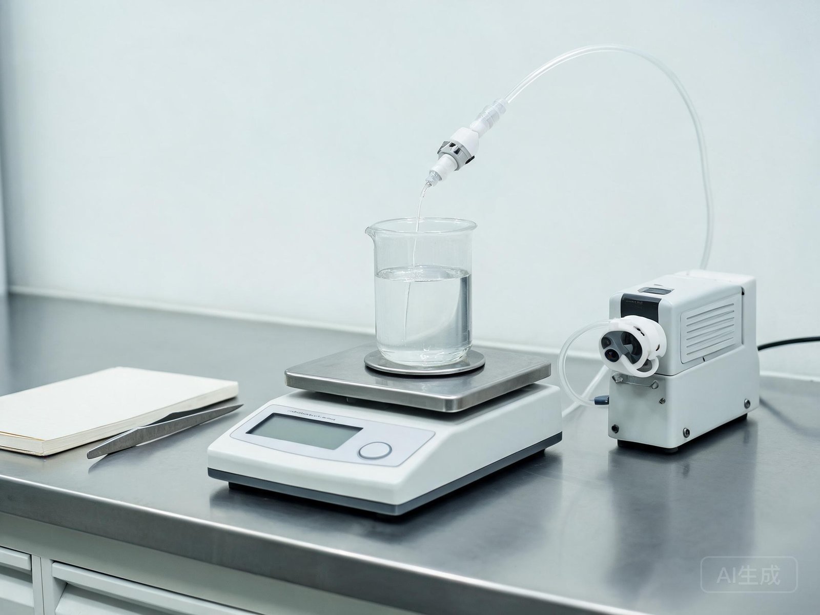
A displayed motor speed is a command, not a measurement of liquid delivered, so the valid calibration reference is mass on a balance, converted to volume using the reagent density. Rigorous measurement practice — including repeated measurements and uncertainty estimation — follows the process-characterization methods described in the NIST/SEMATECH engineering statistics handbook’s measurement process section, and the flow-measurement references maintained through the NIST fluid metrology program provide the underlying volumetric basis. The Hydraulic Institute standards resources are useful when writing the result into a formal test specification.
| Step | Action | Record |
|---|---|---|
| 1 | Prime fully with the actual reagent at the operating temperature; bleed all inlet air | Reagent, lot, temperature |
| 2 | Set the pump to its normal production speed — not a calibration-only speed | Speed setting / step count |
| 3 | Dispense at least 5 (preferably 10) fixed shots into tared vessels on a calibrated analytical balance | Mass of each shot |
| 4 | Convert mass to volume with reagent density; calculate mean and coefficient of variation | Mean dose, CV%, spread |
| 5 | Update the controller’s volume coefficient from mean error; never edit only one outlier shot | Old and new coefficient |
| 6 | Run 3 verification shots; confirm mean and spread both sit inside the method tolerance | Pass/fail against instrument spec |
| 7 | Label the pump with tube size, material, lot and calibration date | Service record entry |
Use a balance whose resolution is at least an order of magnitude finer than the dose tolerance, and recalibrate after every tube change, every reagent change, and at the preventive-maintenance interval. If calibration holds after a tube change but drifts only after a fixed number of run-hours, the tube service interval is the variable to manage — shorten it. If a brand-new, correctly sized tube cannot be calibrated into tolerance at any reasonable speed, the problem has moved out of the consumable layer (drive, mechanics or suction circuit) and the pump should be inspected rather than corrected again. For the underlying relationship between speed, tube size and output used to set the first estimate before calibration, see the article on peristaltic pump flow rate calculation. Mechanical wear patterns that shorten tube life are catalogued in the tubing failure diagnosis guide.
Quick Reference Card
- Slow, weeks-long drift: fatigued tube — replace on run-hours, recalibrate, log the lot.
- Sudden shift after service: wrong tube size/material or unseated occlusion — verify before touching electronics.
- Temperature-correlated error: viscosity and tube stiffness — calibrate at the operating temperature.
- Scatter with pulse sensitivity: evaluate the four-roller K15 against the two-roller unit.
- New tube will not calibrate: inspect drive, back-pressure and inlet side; stop adjusting the coefficient.
- Demand above 350 mL/min: move to the K25 platform or the YZ15 head instead of overspeed-running the K15.
Next step: if an analyzer K15 cannot be brought back into tolerance, send YOORAIN the symptom record — tube size and material, run hours, five gravimetric shot masses, speed setting, reagent and temperature — and the engineering team will diagnose whether the fix is a configuration change, a roller-pack conversion, or a step up to the next pump size, with a written recommendation before any replacement order.