
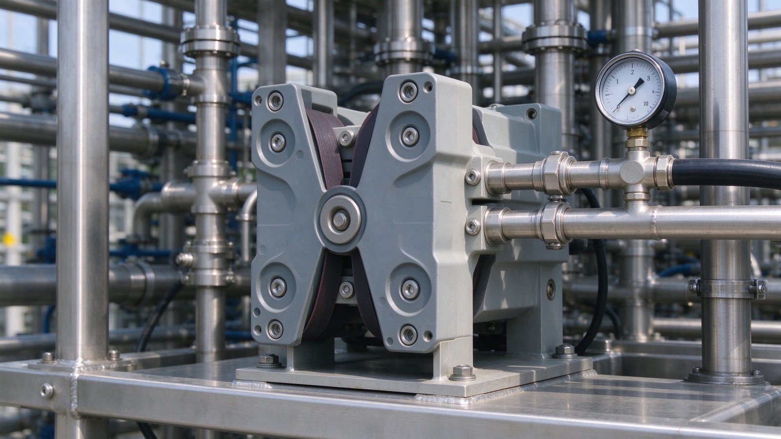
When engineers size a peristaltic pump, they usually start with the flow rate: how many liters an hour, what tube bore, what speed. That gets the head roughly right, but it does not tell the whole story. A peristaltic is a positive-displacement pump, and positive-displacement pumps do not care that much what the fluid tastes like, but they do care a lot about what is sitting on the discharge side. A clogged filter, a narrow nozzle, a valve held partly closed, a tall riser, or another pump pushing back all raise the back-pressure the peristaltic has to overcome. If that pressure is higher than the head and tube can hold, flow drops, the tube fatigues faster, and the pump can look weak even though the speed reading looks correct. This engineering guide explains where peristaltic pressure comes from, what limits it, how back-pressure changes the delivered flow, and how to read the pressure side before you commit to a pump.
How a Peristaltic Pump Develops Pressure
A peristaltic pump moves fluid by rolling a compressed section of tube along the pump body. The roller pinches the tube closed, and the trapped fluid ahead of that closed section is pushed toward the discharge. The pressure at the discharge is the force the compressed tube can transmit to the fluid, divided by the tube bore. Unlike a centrifugal pump, which lets flow slip back internally as pressure rises, a peristaltic is positive displacement: each revolution traps a slug of fluid and moves it out. The catch is that this displacement only holds up to the point where the tube can no longer seal against the roller, the tube wall can no longer hold the pressure, or the motor runs out of torque.
The peristaltic pump tube is the pressure-bearing component. It closes fully under the roller, and that closed seal is what builds pressure. If the tube is worn, swollen, soft, or under-compressed, the seal leaks back on the pressure side and pressure falls before the rated flow is reached. The peristaltic pump driver supplies the torque to squeeze the tube against the load; a driver that runs out of torque stalls or slows down under a heavy discharge load. Neither the tube nor the driver can be judged without knowing the back-pressure the line actually puts on the pump.
What Sets the Pressure Ceiling
A peristaltic pump is generally considered a low-to-moderate pressure pump compared with piston or gear metering pumps. The actual pressure a given head can hold is specific to the tube material, wall thickness, bore, roller geometry, and motor torque, and it should be confirmed against the specific head datasheet rather than quoted as a single universal number. Four things bound that ceiling.
| Limiting factor | What happens as pressure rises | What to check |
|---|---|---|
| Tube seal under roller | Worn or soft tube leaks fluid back past the roller, pressure and flow drop | Tube condition, occlusion adjustment, tube hardness |
| Tube wall strength | High pressure stretches or bulges the tube, accelerates fatigue, risks split | Tube material and wall rating for the fluid and pressure |
| Motor torque | Heavy load slows or stalls the driver, current rises, heat builds | Driver torque margin, gear ratio, current draw under load |
| Head geometry and bore | Larger bore heads move more fluid but trade pressure for displacement | Head size matched to flow and pressure together |
The takeaway is that pressure and flow are chosen together. A head sized only for liters per hour, on a line with a high back-pressure, will either under-deliver or wear the tube quickly. A small peristaltic pump on a short, open discharge line behaves very differently from the same head pushing through a filter and a long riser.
How Back-Pressure Changes the Delivered Flow
On a positive-displacement pump the theoretical displacement per revolution is fixed by the head and tube bore. In real service, some fluid slips backward past the roller under pressure, and that slip grows as the discharge pressure rises. The result is that delivered flow at the set speed is lower on a high-back-pressure line than on an open line. This is why a bench calibration done with the tube running free in a bucket does not match the installed flow on a closed system with a filter, nozzle, or downstream pressure.
Pressure also feeds back into tube life. Every compression cycle at high back-pressure loads the tube wall harder. A tube that lasts a long time on an open discharge can fatigue, crack, or swell sooner on a restricted line. The motor-driver operating manual treats load and heat as linked: a driver pushing against high pressure draws more current and runs warmer, which shortens motor life on continuous duty.
| Back-pressure source | Typical cause | What to inspect |
|---|---|---|
| Static discharge head | Pump feeding a tank or riser above the pump level | Vertical lift from pump centerline to discharge point |
| Line friction | Long, thin discharge tubing or many bends and fittings | Tube inner diameter, length, bend count, fitting restriction |
| Filter or strainer | Clogged filter catching solids or polymer residue | Filter condition, scheduled cleaning, bypass or bleed |
| Restriction downstream | Partly closed valve, small nozzle, injector or eductor | Valve position, nozzle size, downstream equipment spec |
| Other pumps in series | Two pumps feeding a common pressurized header | Header pressure, check valves, pump interaction |
| Viscous fluid | Thick fluid resists flowing through the line | Fluid viscosity, bore, speed, whether heating is needed |
Suction Side Pressure Is the Mirror Image
Pressure problems show up on the discharge, but they often start on the suction side. A peristaltic creates suction by opening the compressed tube back up; if the suction line is thin, long, clogged, or lifting from too deep, the pressure inside the tube on the inlet side drops below atmospheric. Under that vacuum, the tube can soften and collapse, the fluid vaporizes where pressure falls below its vapor pressure, and the pump draws air instead of liquid. The suction-lift and tube-collapse failure mode is documented separately, but it belongs in any pressure review because a starved suction side behaves like a weak discharge side: low flow, pulsing delivery, erratic reading.
Keep the suction line short, smooth, and generous in bore, and avoid restrictive suction filters where possible. Prime the pump on installation so the tube fills before pressure builds on the discharge. The NIST physical measurement laboratory guidance on fluid measurement applies here as elsewhere: measure the delivered volume gravimetrically under the real installed conditions, not on a free-flow bench.
Measuring the Discharge Pressure
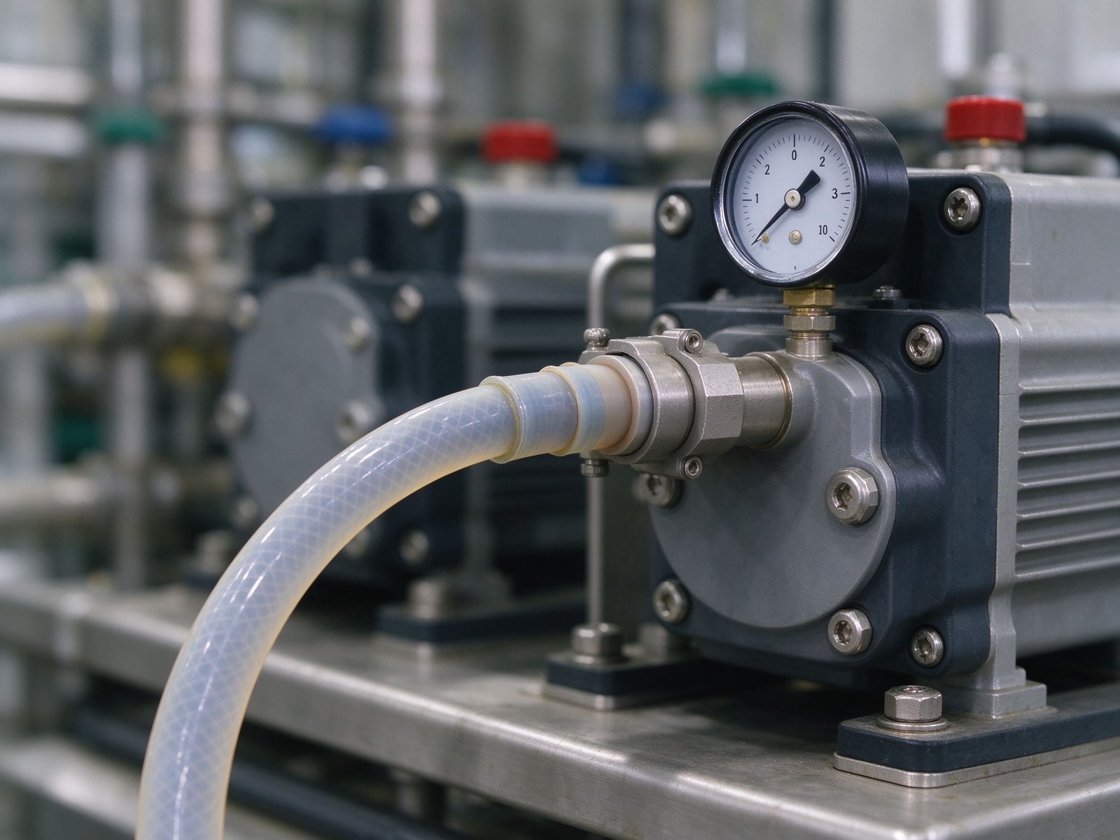
The cheapest way to know whether back-pressure is the problem is to put a gauge on the discharge side, close to the pump, and read it under running conditions. Compare the reading against what the line and downstream equipment require. A gauge that climbs as the line clogs, or that swings hard with each revolution, tells you more than the speed setting alone. On metering or filling duties, record pressure alongside delivered volume so a slow rise in back-pressure can be spotted before the flow drops out of spec.
Where the fluid is corrosive, a gauge mounted through a suitable isolation or diaphragm arrangement protects the instrument; where pulsation makes the needle swing, a small dampener or a snubber keeps the reading steady. The NSF fluid-handling engineering guidance treats instrumentation and isolation as part of a reliable chemical-feed system, not an optional extra.
Pressure-Related Symptoms and Diagnosis
| Symptom | Likely pressure-side cause | First check |
|---|---|---|
| Flow lower than set speed suggests | Back-pressure too high, slip past roller | Discharge gauge, filter, nozzle, valve position |
| Tube splits or bulges early | Pressure above tube rating, swollen chemical | Tube material compatibility and pressure rating |
| Driver stalls, current high, warm | Torque overload on restricted line | Load pressure, driver torque margin, gear ratio |
| Pulsing or intermittent flow | Suction starvation compounding discharge load | Suction line, prime, tube collapse on inlet |
| Pressure reading drifts up over time | Filter or line clogging as solids build | Filter maintenance, strainer condition |
| Flow drops after thickening fluid | Viscosity raising line resistance | Fluid viscosity, bore size, speed, line size |
Discharge Line Design Practices
A few design choices keep back-pressure within what the head and tube can handle. Size the discharge line so friction loss stays low over the expected flow; a line that is too thin converts useful pressure into heat and turbulence. Place valves and restrictions where their effect is understood, and avoid adding a narrow nozzle or injector without checking its pressure drop. Leave access for a gauge and, where the fluid could overpressure the line, a relief or bypass arrangement that protects the tube and downstream equipment. On multi-point feed, make sure each branch valve is set so one closed branch does not load the whole pump against a dead end.
For higher-flow duties, a large-flow peristaltic pump moves more fluid per revolution but still has a pressure ceiling set by its tube and driver; flow size and pressure rating have to be reviewed together. For small chemical feed, the 24V dosing pump head is sized against the chemical line’s back-pressure before the driver speed is set.
Temperature and Pressure Behavior
Temperature changes how the tube holds pressure, and it is easy to overlook on a process line. A tube running warm softens and seals less firmly against the roller, so slip past the closed section rises and delivered flow falls at the same speed. A tube running cold stiffens, which raises the force the driver needs to compress it and can push the motor toward its torque limit. Chemical concentration also matters: a fluid that concentrates as water evaporates from an open reservoir becomes more viscous and more aggressive on the tube, raising both line resistance and chemical load over the day. When reviewing pressure, note the fluid temperature at the pump and whether it drifts between morning and afternoon, because a tube that seals well at room temperature may lose pressure once the line warms up.
This is also why tube material selection and pressure review go together. A material that swells or hardens in the chemical changes its compression characteristics over time, which shows up as a slow rise in back-pressure or a slow drop in delivered volume. If the process runs hot, cold, or through a wide seasonal range, that should be stated up front rather than assumed away.
Protecting the Pump Against a Dead-End Discharge
Because a peristaltic keeps displacing fluid against whatever it meets, a blocked discharge is the most direct way to overload the head. A valve closed for maintenance, a filter fully plugged, a frozen line in cold weather, or an injector that blocks all drive pressure back onto the tube. On a positive-displacement pump the pressure does not settle at a system curve the way it would on a centrifugal; it climbs until something gives. The protective measures are therefore mechanical and procedural, not a software speed reduction alone. A relief or bypass line that returns fluid to the suction reservoir, a pressure switch that cuts the driver when pressure crosses a set point, and a clear lockout procedure for closing discharge valves all reduce the chance of an overload event. On unattended skids, low-level and pressure alarms give notice before the tube or driver takes the load.
It helps to think through a typical line before ordering the pump. Start with the fluid and its viscosity, add the static lift to the discharge point, lay out the actual line bore and length with its fittings and bends, and then list every restriction on that line: filter, nozzle, injector, downstream valve, any header held under pressure. Summing those gives the back-pressure the pump must overcome at the target flow. Where any of those items is unknown, treat the pressure as an estimate to confirm after installation, and leave the head and driver a margin rather than sizing them to the lowest possible pressure reading.
Common Questions
Is a peristaltic pump a high-pressure pump? No. Peristaltic and tubing pumps generally serve low-to-moderate discharge pressure duties. If your line needs a high discharge head or pushes against a pressurized header well above the pump’s rating, a piston, plunger, or diaphragm metering pump is usually the better fit.
Does closing a valve on the discharge damage the pump? A positive-displacement pump keeps trying to move fluid against a closed valve, so pressure climbs until the tube slips, the driver overloads, or a tube or fitting gives way. Never throttle a peristaltic with a downstream valve as a speed control; use the driver speed instead, and protect against an accidental dead end with relief or bypass.
Why does my flow fall after the filter clogs? A clogged filter raises the back-pressure on the pump. Slip past the roller increases, delivered volume drops, and the driver draws more load. Cleaning or replacing the filter restores both flow and torque.
Can I raise the pressure by using a stiffer tube? A stiffer tube can seal better and hold its shape, but it also loads the rollers and motor harder and changes the compression required. Tube choice balances pressure seal, fatigue life, and drive torque, and should be matched to the fluid rather than picked only for stiffness.
How do I know the pressure my line actually imposes? Measure it. Fit a gauge near the discharge, run the real fluid at the real flow, and read the steady pressure. Include the static lift, filter condition, and any downstream nozzle or injector in that reading.
What to Tell the Supplier Before Sizing
When you ask for a pump recommendation, give the supplier the discharge conditions as well as the flow: the fluid and its viscosity, the vertical discharge lift, the discharge line length and bore, any filter, valve, nozzle, or downstream pressurized equipment, and the operating hours per day. With that, the head, tube material, and driver torque can be matched to both the flow and the pressure instead of to the flow alone. The peristaltic pump driver reference and the EPA industrial water management guidance both support reviewing the whole fluid path, not just the head.
If you are sizing a peristaltic and are unsure how much back-pressure your line puts on the pump, contact YOORAIN with the fluid, target flow, discharge height, line bore and length, and any filters or restrictions on the discharge side. We can review whether the proposed head and driver hold the pressure margin you need, and suggest the tube material and line configuration that keep both flow and tube life in range.