
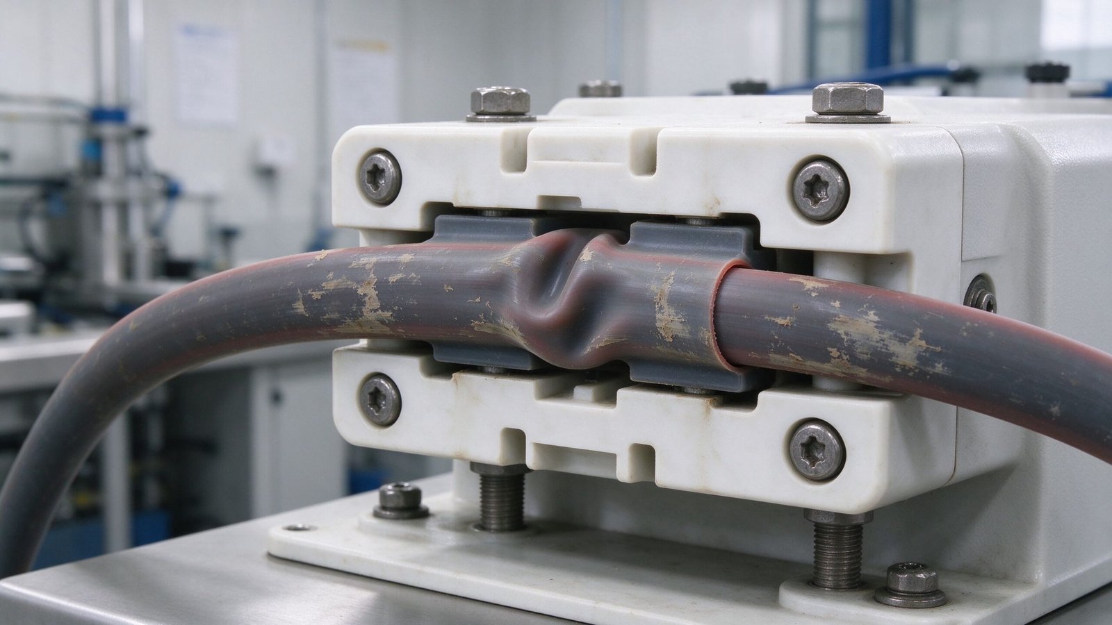
In a peristaltic pump, the tube is the wearing part. Every roller pass bends and compresses it, and after enough passes the material fatigues, thins, and eventually cracks or bursts. Tube life is not a fixed number printed on a datasheet; it is the result of how hard the pump squeezes the tube, how fast it runs, what the fluid is, and how the head is adjusted. This reference explains how tube fatigue actually works, what shortens life, how to estimate a replacement interval, and what an OEM or maintenance team can do to make the tube last predictably rather than failing unexpectedly.
How a Peristaltic Tube Wears
The tube is deformed on every revolution. A roller presses the tube flat against the pump bed, sealing the fluid path, then releases it so the tube can spring back and draw in the next bolus. Repeated compression and recovery is the mechanism that moves fluid, but it is also the mechanism that ages the tube. Two things happen at once: the elastomer slowly loses its elastic recovery (compression set), and the wall material at the occluded point develops small fatigue cracks that grow with each cycle.
The visible signs of aging are gradual. The tube may become slightly softer or stiffer, the compression marks from the rollers become more pronounced, and the delivered volume drifts because the tube no longer seals as well. The end point is a small crack at the occluded point, which begins to weep and then bursts. A tube rarely fails without warning, but the warning is easy to miss if nobody checks the tube.
The Main Factors That Set Tube Life
Several variables decide how many hours a tube will last, and they interact rather than act independently.
Occlusion (compression depth). This is the strongest lever on tube life. A tube that is squeezed just enough to seal lasts far longer than one that is over-compressed. Over-occlusion is the most common cause of short tube life, because it forces the elastomer past its elastic limit on every pass. The correct occlusion is the minimum compression that still seals the fluid path at operating pressure.
Pump speed. A tube running at high speed bends more times per hour, so fatigue accumulates faster. Doubling the speed roughly doubles the number of compression cycles in a given time, and life in hours drops accordingly. This is why a pump run at a fraction of its rated speed lasts much longer per hour than one run flat out.
Tube material. Different elastomers fatigue at different rates and resist different fluids. A material that is ideal for water may be attacked by a solvent, which both shortens life and changes its compression behavior. The peristaltic pump tube must be matched to the fluid, not chosen on cost alone.
Fluid temperature and chemistry. Heat accelerates fatigue and softens the elastomer. Aggressive fluids swell, harden, or chemically attack the tube wall. A hot solvent in an incompatible tube will fail far sooner than the same tube with cool water.
Back-pressure. Higher discharge pressure forces the roller to work harder and increases the stress on the tube at the sealing point. Excessive back-pressure is a common reason a tube fails early in an otherwise well-adjusted head.
| Factor | Effect on tube life | Typical response |
|---|---|---|
| Over-occlusion | Greatly shortens life | Set minimum sealing compression |
| High speed | More cycles per hour | Oversize the head, run slower |
| Incompatible material | Swelling / hardening / cracks | Match tube to fluid chemistry |
| Elevated temperature | Accelerates fatigue | Lower speed, cool the fluid |
| High back-pressure | Higher sealing stress | Reduce restriction, check nozzles/filters |
How Occlusion Is Set
Occlusion is the amount the tube is flattened when the roller passes. Too little and the tube back-flows, which hurts accuracy and priming. Too much and the tube fatigues quickly. Pump heads designed for OEM use provide an adjustable occlusion, and the correct procedure is to set it just enough to stop back-flow at the operating back-pressure, not to crank it down until the tube is visibly crushed.
For a given head and tube, there is a narrow band of compression that seals reliably without over-stressing the elastomer. A common mistake is to increase occlusion because flow seems low; the real cause is often a worn tube, a suction leak, or a speed that is too low for recovery. Tightening the head treats the symptom and destroys the tube.
Estimating a Replacement Interval
Because tube life depends on the application, the reliable way to set a replacement interval is to run the actual pump in the actual duty cycle and measure. The process is straightforward: install a new tube, run the pump under real conditions, and check it at intervals while tracking the delivered volume. The point where volume starts to drift noticeably, or small cracks appear, is the end of useful life. Set the replacement interval to a safe fraction of that observed life, so the tube is changed before it can fail in service.
| Observation | What it tells you |
|---|---|
| Volume drifts down over time | Tube losing seal, approaching end of life |
| Tiny weep at occluded point | Crack forming, replace now |
| Tube feels softened or swollen | Chemical attack, change material |
| Tube hardened / discolored | Heat or chemical aging |
| Consistent life across many units | A safe interval can be defined |
This observed-life approach beats a generic datasheet estimate, because the datasheet number is usually for water at room temperature with a defined head. In real duty cycles, the interval is set by the customer’s fluid and speed. Engineering measurement practice of this kind, where a parameter is tracked under real operating conditions, follows the metrology principles that NIST’s Physical Measurement Laboratory supports: record the conditions, measure the change, and set the limit from data rather than from a guess.
How to Make Tubes Last Longer
There are several practical levers. Run the pump at the lowest speed that meets the required flow; a larger head with a bigger tube run slowly outlasts a small head run fast. Set occlusion to the minimum sealing value. Keep the fluid cool and reduce back-pressure by shortening the discharge line and avoiding clogged filters or nozzles. Use the tube material recommended for the fluid, and specify it as a calibrated consumable rather than a generic part.
For continuous-duty equipment, choosing the right head size matters. A compact small peristaltic pump running within its comfort band will outlast a head pushed beyond its design speed. For larger flows, a large-flow peristaltic pump run at moderate speed gives the tube a gentler duty cycle. Matching the head to the duty cycle, rather than buying the smallest pump that can just reach the flow, is one of the cheapest ways to extend tube life and reduce unplanned stops.
The Cost of Unexpected Tube Failure
A burst tube is more than a parts change. It spills fluid, stops the process, and can contaminate the equipment. In a dosing instrument, an unplanned burst means a missed batch or a failed measurement. In a process line, it means downtime and cleanup. This is why a defined replacement interval and a visible drift check pay back: they turn tube life into a planned maintenance event instead of a failure event.
For an OEM product, the maintenance story is also a selling point. A pump whose tube can be changed in seconds, with no tools and no pump teardown, lowers the cost of ownership. The motor and head are long-lived; only the tube is consumed, and that consumable is inexpensive. Drivers and controls, as described in common OEM motor-driver operating manuals, do not wear with the tube, so the replacement interval is purely a tubing decision. Stepper-based heads, with their defined speed-control input, let the instrument slow the pump when tube wear begins to affect flow.
How Speed and Back-Pressure Compound
Speed and back-pressure do not act independently, and that is where many premature tube failures come from. A pump run fast bends the tube more times per hour, and a pump pushing against a high back-pressure stresses the sealing point harder. When both are present, the tube fatigues faster than either factor alone would suggest. A high-speed pump on a restricted discharge line is the worst common combination, because the tube is being cycled quickly and squeezed hard at the same time.
The practical response is to look at the whole system, not just the head. Shorten the discharge line, remove unnecessary filters or shut-off valves, and use a nozzle that does not introduce an artificial restriction. Then choose a head that reaches the required flow at a lower speed. Two pumps can deliver the same nominal flow, but the one that does it at half the speed, against a clean discharge path, will put far less stress on the tube. This is why system design, not pump selection alone, decides tube life.
The suction side matters as well. A long, narrow intake, a high lift, or a viscous fluid makes the tube work harder to refill, and starving the intake creates pulsing flow that hammers the tube. Keeping the intake short and unrestricted helps the tube recover fully between rollers, which both improves flow and reduces the uneven loading that accelerates fatigue.
The Cost of Getting Occlusion Wrong
Occlusion is the one adjustment that technicians often get wrong, and both errors are costly. Too little occlusion causes back-flow, poor priming, and low flow, which leads operators to compensate by tightening the head. Too much occlusion, as noted, destroys the tube. The correct procedure is to set the head to the minimum compression that seals at the operating back-pressure, and then to leave it alone. When flow drops, the cause is more often a worn tube or an intake leak than an occlusion that was set too low.
For OEM equipment, this argues for heads with a defined, repeatable occlusion setting rather than a free-adjustment screw that every installer sets differently. A head whose tube and bed geometry are matched, and whose compression is fixed by design, removes the technician variable from tube life. The maintenance procedure then becomes a clean tube swap with no adjustment to redo.
Common Questions
Can I run the tube until it bursts? No. By the time it bursts, the volume has already drifted and the process may have produced off-spec product. Change the tube on schedule, not on failure.
Does a higher-quality tube always last longer? It lasts longer when it is matched to the fluid and correctly occluded. The best material in the wrong application, or over-compressed, fails fast.
How often should I inspect the tube? On continuous-duty equipment, inspect at the planned maintenance interval; on intermittent equipment, check whenever the process is opened. A short visual check of the occluded point catches cracks early.
How Fatigue Cracks Actually Develop
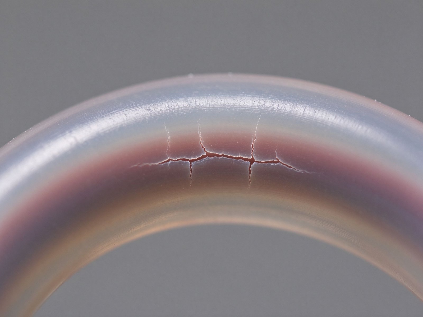
The failure does not happen at once. It starts as tiny cracks on the compressed side of the tube wall, where the material is stretched most on each roller pass. At first the cracks are microscopic and only visible under magnification. Over thousands of cycles they grow across the wall thickness, and once a crack reaches the inner surface, the fluid begins to weep through it. Because the tube is under compression at the sealing point, the weep often starts as a slow dampness around the head rather than a dramatic spray.
This is why a visual inspection of the occluded point matters. A tube that looks fine from the outside can have a crack developing on the wall that contacts the roller. The inspection should look at the compression line where the roller seals the tube, not just at the exterior. Cracks that begin there progress to a burst, and the burst happens at the sealing point where the material is most worked.
Tube Materials and Fatigue Resistance
Different elastomers have different fatigue lives, and the choice is always a trade-off between chemical resistance and mechanical endurance. A general-purpose silicone tube recovers well and is a common baseline, but its fatigue life and chemical limits vary by formulation. A high-performance elastomer may resist aggressive chemicals but be stiffer, which changes occlusion and can shorten fatigue life if the head is not adjusted for it.
| Material class | Mechanical / fatigue behavior | Typical use |
|---|---|---|
| General-purpose silicone | Good recovery, common baseline fatigue life | Water-like, mild fluids |
| Chem-resistant tubing | Stiffer, needs correct occlusion | Solvents and aggressive chemicals |
| Pharma-grade tubing | Consistent wall, predictable fatigue | Reagent and clean transfer |
| Heat-cured specialty tube | Stable compression, longer measured life | Continuous-duty metering |
The practical point is that the datasheet fatigue number is only meaningful for the head, speed, fluid, and temperature under which it was measured. A tube that lasts hundreds of hours with water may last a small fraction of that with a hot solvent. Treat the observed life in the actual application as the real number, and use the datasheet only as a starting point.
Duty Cycle: Continuous vs Intermittent
A tube that runs continuously accumulates cycles steadily, and its life is measured in running hours. A pump that runs for a few minutes an hour accumulates far fewer cycles, so its tube lasts much longer in calendar time even though the running-hour life is similar. This matters when quoting a replacement interval: a 24-hour dosing pump and an intermittent lab pump will not have the same maintenance calendar, even with the same tube.
For continuous-duty equipment, oversizing the head is the most effective way to extend tube life. A larger head run slowly bends the tube fewer times per unit of flow, which reduces the cycle rate. A head run near its maximum speed to reach a required flow is working the tube hard. Choosing a head that delivers the needed flow at a modest speed, and a motor and driver that can hold that speed steadily, pays back in longer tube life and fewer unplanned stops. The peristaltic pump driver chosen should match the motor and allow the pump to run at that gentle operating point.
Monitoring Tube Wear in Service
Rather than waiting for a weep, the instrument can watch for the signs of wear. The most practical signal is the slow drift in delivered volume: as the tube loses its seal, the per-revolution volume drops. A periodic check dispense against a known target flags this drift, and when it crosses a threshold, the system schedules a tube change. This turns maintenance into a planned event tied to the actual condition of the tube, not to a calendar estimate.
A leak or weep sensor near the head adds a second layer of protection for continuous process equipment. It catches the early weep that precedes a burst, so the pump can be stopped before fluid spills. Together, a volume-drift check and a leak sensor cover the two ways a worn tube announces itself: gradually, through changing flow, and suddenly, through weeping at the seal.
What to Specify for Predictable Tube Life
- Define the duty cycle: hours per day, speed, and back-pressure.
- Match the tube material to the fluid chemistry and temperature.
- Set occlusion to the minimum sealing compression, not tighter.
- Oversize the head so the pump runs below its maximum speed.
- Measure observed tube life in the real application, then set a safe replacement interval.
- Add a drift or leak check that flags a worn tube before it bursts.
If you are specifying peristaltic pumps for continuous-duty equipment and need help estimating tube life under your duty cycle, contact YOORAIN with the fluid, flow rate, hours per day, and back-pressure. Those details let a supplier recommend the head size, tube material, and control strategy that keep tube replacement a planned event rather than an unexpected stop.